Advanced settings
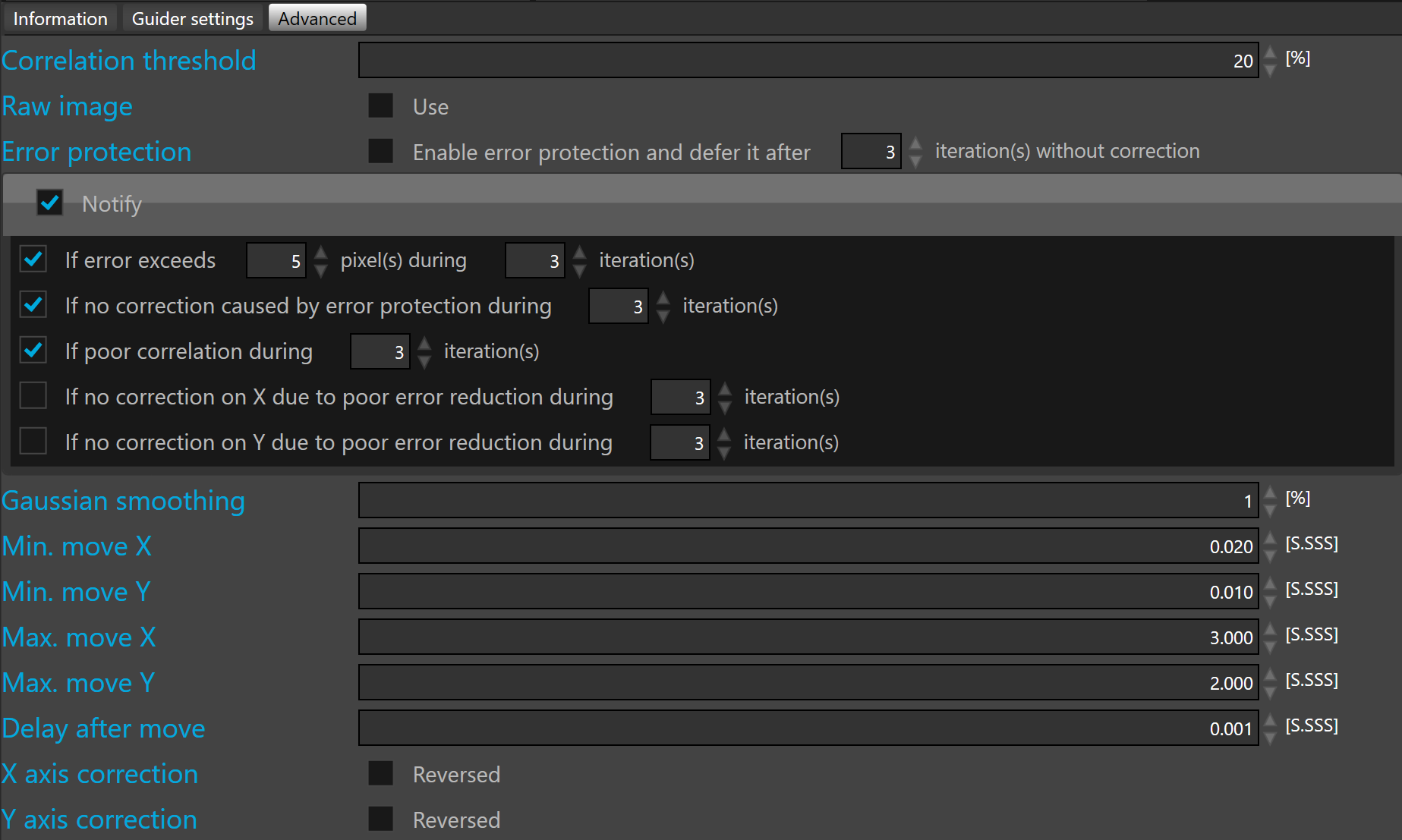
Correlation threshold defines the minimum value before suspending guiding. By default the correlation threshold is 50%.
 Below this threshold SKG automatically suspends the guiding in situations such clouds passing by, or poor SNR.
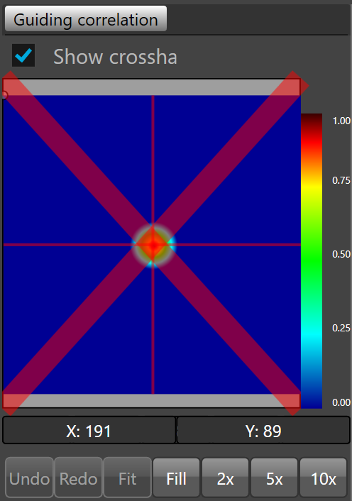
When the correlation is below the threshold, a red cross is displayed on the guiding correlation view port indication that SkG will not use this information to send any correction to the mount anymore.
Raw image check box allows the display of raw correlation in the viewport.
Error protection check box allows prevention of corrections caused by unexpected transient events.
Unexpected transient events are wind gusts, cables tangling, bumping the mount, unlocked axis clutch or any event causing a large, quick and expected move of the guider FOV.
The error protection can be deferred after a predefined number of iterations. By default 3 iteration.
 Once the number of iteration is reached the corrections are resumed.
Notify allows notification in the case of abnormal guiding conditions.
To be notified by push notification directly on a smartphone, notification must be configured.
Five distinct abnormal guiding conditions can be set up:
- If error exceeds a predefined number of pixels during a predefined number of iterations
- If no correction is caused by error protection during a predefined number of iterations
- If poor correlation during a predefined number of iterations
- If no correction on X due to poor error reduction during a predefined number of iterations
- If no correction on Y due to poor error reduction during a predefined number of iterations
To enable each condition, check the check box on the left side.
Once checked, define the conditional parameters.
To enable/disable all notifications, check/uncheck the notify check box.
Gaussian smoothing smooths the correlation peak removing noise which may lead to erratic peak detection.
It is a low pass filter. This value specifies the percentage of low pass peak processing.
By default, Gaussian smoothing is set to 10%.
Min. move X allows definition of the lower limit of a single move on the X axis. By default, 0.02 second.
Min. move Y allows definition of the lower limit of a single move on the Y axis. By default, 0.02 second.
 If the correction is lower than this limit, then there is no correction output to the guider relay.
With a good mount (like those having high resolution encoders) we recommend to set the minimum move to zero.
Max. move X allows definition of the upper limit of a single move on the X axis. By default, 3 seconds.
Max. move Y allows definition of the upper limit of a single move on the Y axis. By default, 3 seconds.
If the correction is higher than this limit, the correction output to the guider relay will be limited to the maximum value.
Delay after move allows definition of a delay between each move on the guider relay. By default, this parameter is set to 0.01 second.
Reverse X axis correction allows reversal of the direction of the correction on the X axis. If this option is enabled, +X becomes -X and -X becomes +X. By default, this option is disabled.
Reverse Y axis correction allows reversal of the direction of the correction on the Y axis. If this option is enabled, +Y becomes -Y and -Y becomes +Y. By default, this option is disabled.
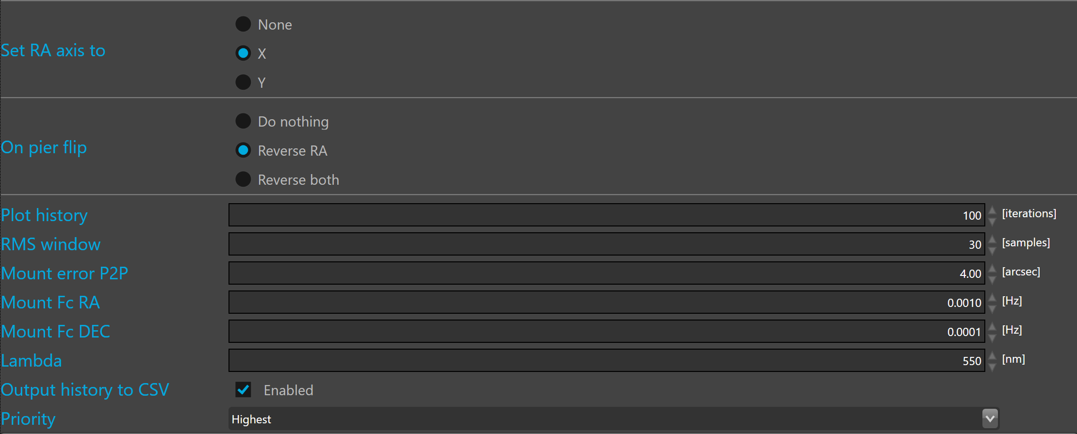
Set RA axis to allows to define with axis is the RA. By default the RA axis is set to X.
This is parameter must be carefully defined because SKG use it to know on which axis the pulse duration must be corrected with the declination. Wrong RA axis definition will affect the guiding stability.
 None must only be used with optical bench or with simulator because when the RA axis is set to none there is no declination correction
On pier flip allows to define which axis will be reversed after the pier flip.
Plot history allows definition of the number of iterations that will be displayed in all plots.
RMS window allows definition of the number of samples required to calculate the RMS values. In most cases 30 samples are enough. The default value is 30 samples.
Mount error peak to peak allows definition of the performance of the mount after PEC correction. The default value corresponds to the average performance of a mid range mount. The default value is 4 arcsec peak to peak.
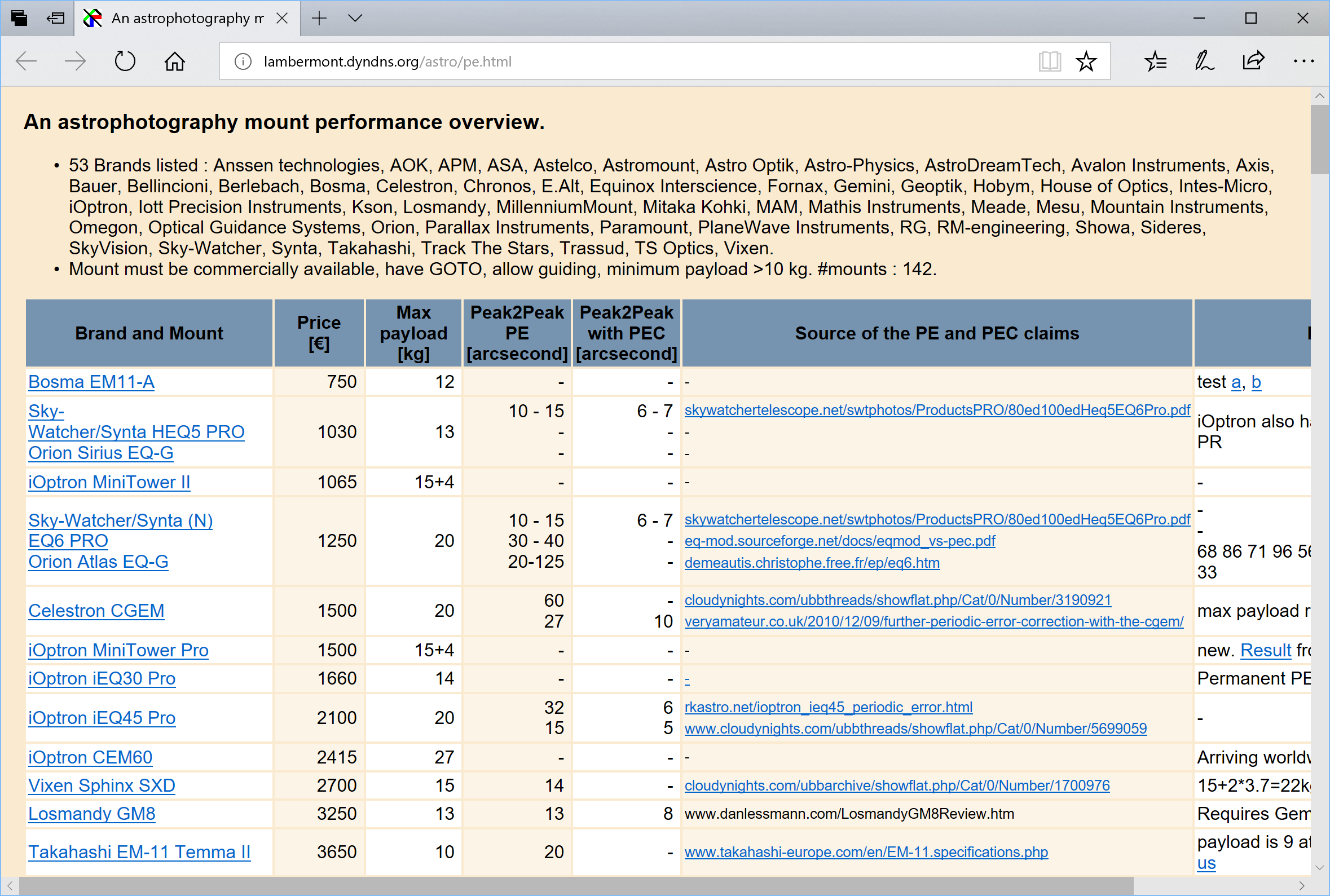
To properly define the peak to peak error of your mount, visit the following Web sites, read the technical data sheet of the mount, or test you rmount after PEC..
This parameter is used by the optimal aggressiveness calculator. It should be set as close as possible to the mount performance.
Mount power spectrum cut-off frequency of -3dB is defined for each axis in Hertz. By default, for the right ascension the value is 0.001 Hz and for the declination, the value is 0.0001 Hz.
This value is related to the mount short term mechanical error (gear-box noise typically) bandwidth. It should not be confused with the mount auto-guiding correction bandwidth capability which is usually much higher.
The default values are generally good for most mounts.
This parameter is used by the optimal aggressiveness calculator.
Lamda is the average wavelength used by the main imager camera at capture. Lambda is in nanometers. The default value is set to the middle range of the visible light at 550 nanometers.
This parameter is used by the optimal aggressiveness calculator. To get optimal aggressiveness, this parameter can be adjusted to the bandwidth that will be used during capture.But for most applications 550nm is a good value.
Output history to CSV allows to write statistics about the guiding into a CSV file.
Priority allows to control the thread priority of the guiding loop. By default set to highest priority.
 Multi-threading priorities is quite sensitive, generally the best is to keep the default priority but with old CPU, sometimes the priority level can be lowered to avoid CPU overload.
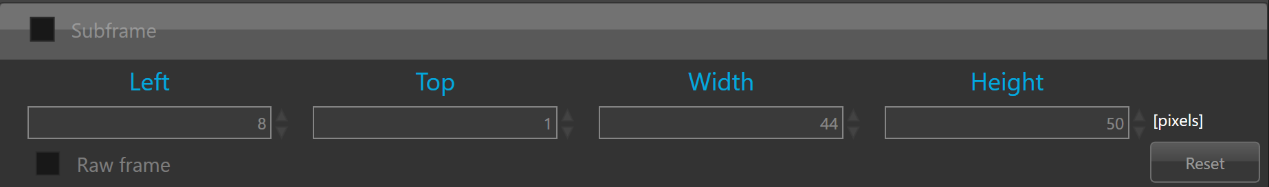
Sub-frame
Guiding input frame can be cropped as a sub-frame.
The subframe can be defined only the the guider camera is connected and acquisition and guiding loops are not running.
Crop window can be defined by editing the value of Left, Top, Width and Height fields but it can also defined interactively on the input view port.
To crop interactively, click the  button.
By default, the frame displayed in the input view port is pre-processed by the SKG algorithms. To display the input raw frame, just check the raw frame check box.
A guider frame exceeding a megapixel cannot be pre-processed, in that case the raw frame will be displayed even if the raw frame check box is not checked.
Once clicked, SKG will capture a new frame from the guider camera and automatically activate the input view port and the tool that allow to define the crop window.
To define the crop window, you must right click on the input view port, hold the mouse down and move it to define the crop rectangle.
Once the crop rectangle looks like what you expected, just release the mouse button to confirm.
To redefine a new crop window, just right click on the camera output and draw a new rectangle.
Once the crop window is defined the Left, Top, Width and Height fields are updated with the rectangle Left, Top, Width and Height.
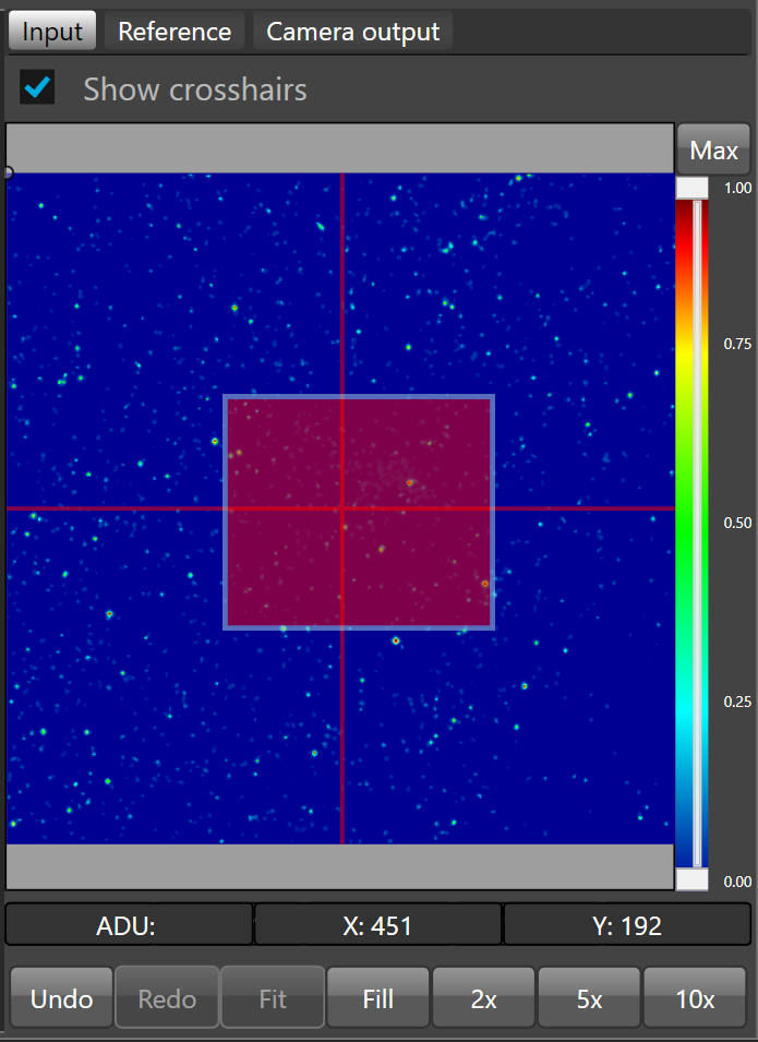
The red rectangle will be the sub-frame.
To crop the guider frame with the defined sub-frame, enable the subframe check box.
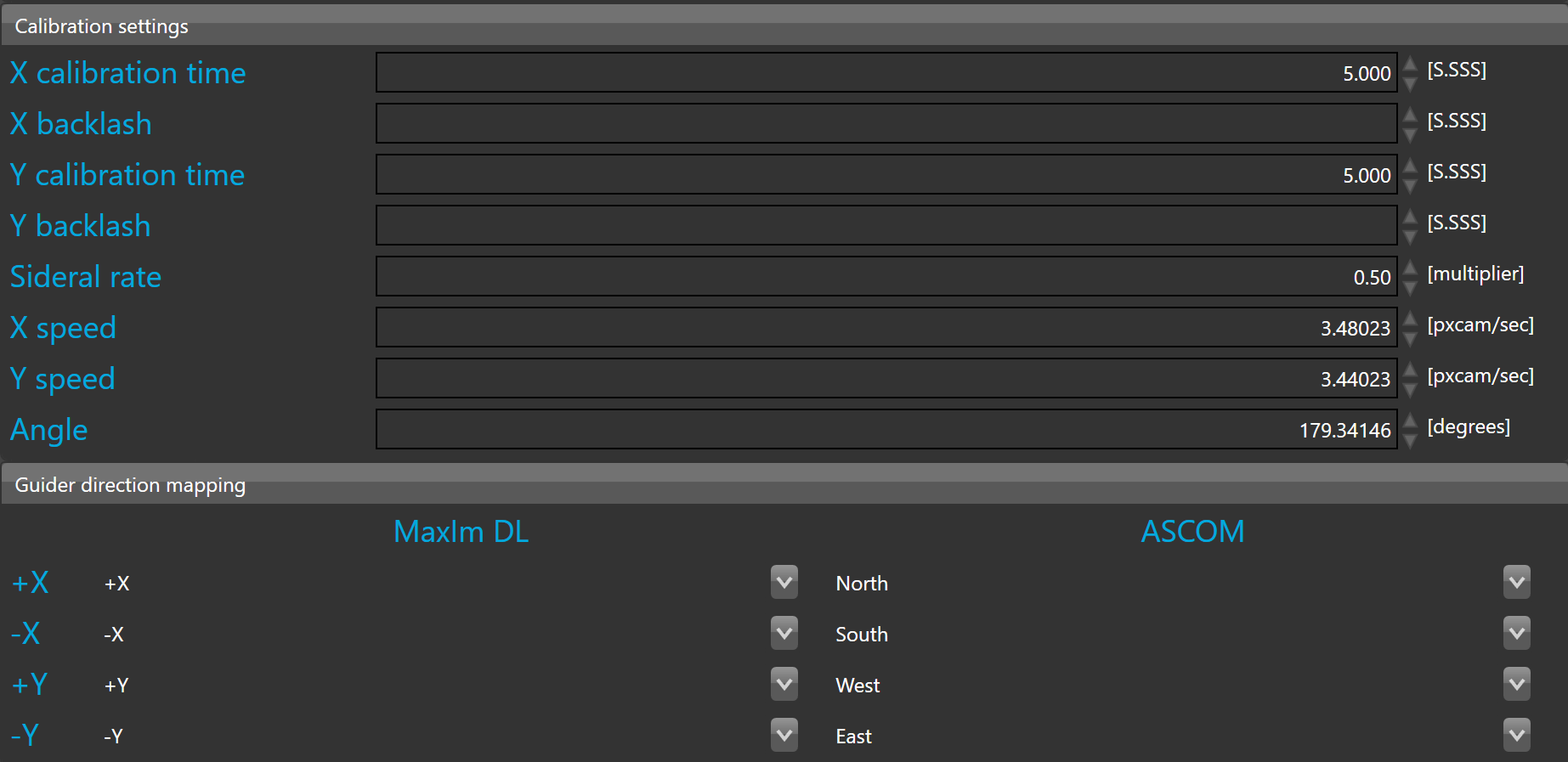
X calibration time and Y calibration time are both used to move the guider during calibration to make the well-known L shape. By default, these parameters are set to 5 seconds.
 Adjust the time to get a move large enough for proper calibration. If this value is too small, calibration will fail. If this happens, increase the time and restart the calibration procedure.
X backlash and Y backlash are both used to compensate the backlash of the mount on both axes.
Sideral rate defines the guider sidereal rate. By default, this is 0.5 of the sidereal time 15.035 arcsec/sec.
If the sidereal rate does not match your mount settings the guider calibration might fail or may lead to unstable auto-guiding.
X speed, Y speed, and angle are calibration settings. These parameters are automatically calculated by the guider calibration procedure.
Guider calibration is very important to get optimal guiding performance. Please take adequate time to follow the recommendations as closely as possible to take full benefit of full frame guiding.
X and Y speed are defined in pixel camera per second. This corresponds to unbinned pixels of the guider camera. The calibration process measures by how many unbinned pixels the guider frame has moved during one second correction pulse (at the set sideral rate, see above).
When the guider has never been calibrated for the selected instrument, the calibration field are empty.
Once your are ready to calibrate just click  button
Guider direction mapping allows mapping of the guiding algorithm correction to the right axis of the guider output relay.
Mapping can be defined for both relays in MaxIm DL and ASCOM.
The mapping is done by default, but can be adjusted if necessary.