Setup your first instruments
Before SKG can be used one needs to define the instrument settings. For SKW specific instrument setting such as, model and request please refer to SKW CT Setup instruments
this aspect is not address here.
One can have more than one instrument settings, this aspect if covered in the advanced features Setup instruments.
 When connecting devices with ASCOM drivers to several clients, such as SKG and an imaging software, those drivers need to feature an hub, multi-clients, capability.
If not sharing the same hardware with several applications may results on unpredictable and unwanted behaviors and system crashes.
In such situation where the ASCOM driver supports only a single client you could sue the OPTEC ASCOM sever to share the device:
https://www.optecinc.com/astronomy/downloads/ascom_server.htm
At the minimum one needs to provide:
- A name for the setting.
- The focal length and the aperture of the scope used for guiding and focusing
- A guiding camera with its source (Guider Output), ASCOM or Maxim-DL
- Which software is in charge of auto-guiding (Guider Control), SKG or Maxim-DL) Full frame guiding is only available with SKG.
- How corrections are send to the mount/telescope (Guider Relay). Though ASCOM (telescope) or the camera ST-4 port. IF Maxim-DL has been selected as Guider Output (see above) then the Guider relay method is selected in Maxim-DL.
 The focuser with its step size in microns per step.
Other settings, such as imager, filter wheel and telescope drivers, are optional (see advanced instrument settings)
If one elects to use the ASCOM telescope option as guider relay (SKG as Guider Output) one need to set up a ASCOM driver for the telescope (mount). One should insure that the PulseGuide features is enabled in the ASCOM driver otherwise SKG cannot send any corrections to the mount.
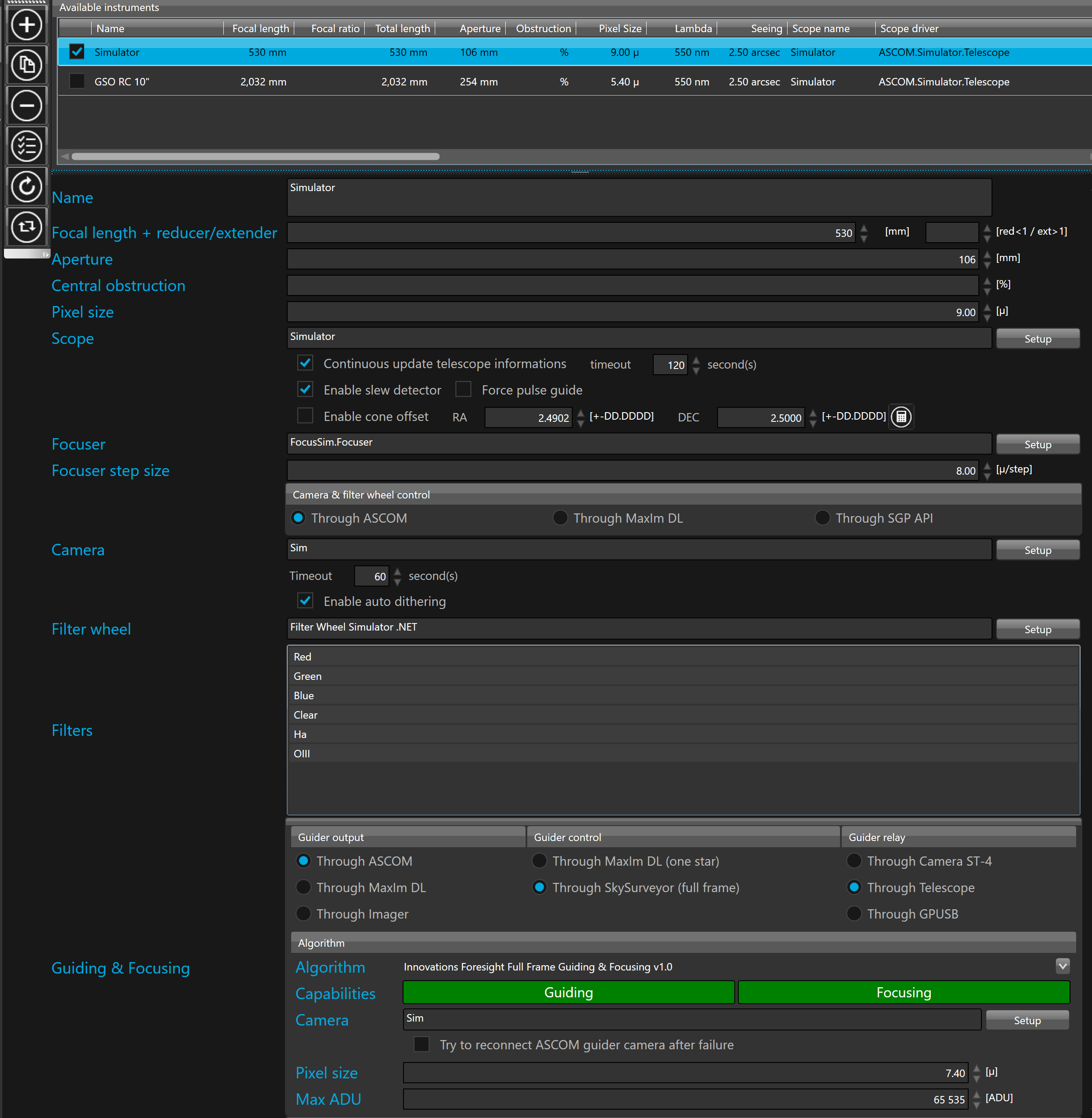
The instrument settings form is divided in 3 zones:
1. A vertical tool bar containing the command buttons that allows to edit the instruments
2. A list of all available instruments
3. A form that allows to configure the selected instrument
For SKW specific instrument setting such as, model and request please refer to SKW CT Setup instruments
this aspect is not address here.
 For security purpose, instruments cannot be edited when at least one instrument is connected. To be able to edit the instrument settings you must disconnect all instruments.
To add a new instrument, click the  button.
Once clicked, a new instrument is added and selected in the available instruments list.
The form that allows editing the instrument parameters automatically displays the newly added instrument.
The first step is to give a Name to your instrument configuration.
Configure your telescope
Focal length in millimeters of the main scope must be defined.
Aperture in millimeters of the main scope must be defined.
To operate focusing capabilities of SkyGuard, the guider camera must be mounted on the guiding port of an ONAG, FOAG with Lacerta for Lodestar from OPTEC or SBIG dual chip camera, the focal length and the aperture must be defined for the main telescope.
 You cannot use a separate guider scope for focusing
Scope allows configuration of the telescope mount, which is optional. Click the  button.
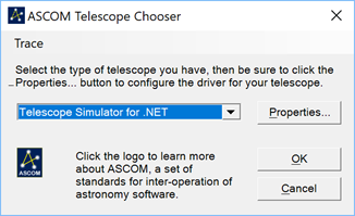
Select the appropriate mount driver in the dropdown list of the “ASCOM Telescope Chooser” and click the “OK” button to confirm.
If your telescope mount is not available in the “ASCOM Telescope Chooser”, it means that there is no ASCOM driver for your telescope mount installed on your computer. To remedy this, find and install the ASCOM driver compatible with your telescope mount. Usually the ASCOM driver can be downloaded from your mount manufacturer’s Web site.
SkyGuard is able to work without connection to any telescope (mount) ASCOM driver. This driver is not mandatory field it can be left empty.
However when the telescope driver is left empty, the target declination and the pier side must be set manually because without connection SkyGuard is unable to determine any of those values for proper auto-guiding. Also slewing detection is not available without connecting to the mount information.
SkyGuard is able to send pulse to the mount through the camera via a ST-4 connector and a cable that wire the camera to the mount or directly to the mount through the telescope ASCOM driver. Hence he telescope ASCOM driver is required to send the pulse through the telescope. If the telescope driver is left empty, the pulses can only be sent through the camera ST4 port or through Maxim-DL is selected as guider relay instead of ASCOM.
 Some ASCOM driver features an HUB allowing multi-client access to a device, such as a camera, a focuser or a mount. If not one can use the ASCOM POTH (for mount, focuser, dome) or the OPTEC ASCOM server.
When Continuous update telescope information check box is checked the information such as the status, pier side, right ascension and declination returned by the ASCOM telescope driver are continuously read out by SkyGuard and displayed in real time in fields that are distributed in the panels of the user interface.
The telescope timeout allows to configure how much seconds SkyGuard will wait to get an answer from the telescope ASCOM driver. An error is raised when the answer from the telescope exceed the given number of seconds.
SkyGuard is able to automatically suspend the guiding operation when the telescope is slewing to another target and after each slew to automatically do the guider settle, to take a new reference frame, and to resume normal guiding operations on the new target without any human interaction.
To activate this option, the Enable slew detector option must be checked.
SkyGuard expose an API (Application Programming Interface) that allows external software to remote control it. Nevertheless, the usage of the API requires an add on in the external software. We are currently working with the leading software manufacturers in order to convince and to help them to implement our API as an add on of their software. Meanwhile, the option such as the slew detector gives SkyGuard the ability to work with external software without API implementation.
Configure the focuser
To achieve auto-focus SkyGuard must be able to move the focuser. It does this with an ASCOM driver.
Focuser allows configuration of the focuser. Click the button.
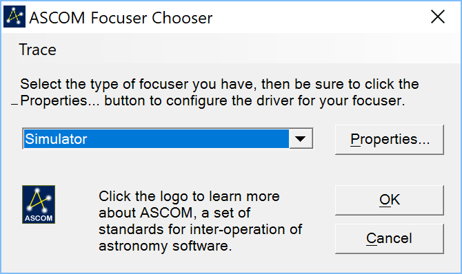
Select the appropriate focuser driver in the dropdown list of the “ASCOM Focuser Chooser” and click the “OK” button to confirm.
If your focuser is not available in the “ASCOM Focuser Chooser” it means that there is no ASCOM driver for your focuser installed on your computer. To remedy this, find and install the ASCOM driver compatible with your focuser. Usually the ASCOM driver can be downloaded from your focuser manufacturer’s Web site.
Focuser step size allows configuration of the number of microns traveled by the focuser on one step.
Usually the ASCOM driver is able to return the size of the step but if not you must input it by hand. The step size is critical to achieve good auto-focus, if a wrong value is entered the auto-focus will produce unexpected behavior.
Configure the imager camera and optionally its filter wheel
SkyGuard is a guiding, it may seem strange to have to configure the main camera. The reason is that SkyGuard is able to read the status changes of the image camera in order to know when to move the telescope for automatic dithering. Thus, each time the camera has completed an exposure, SkyGuard moves the telescope according to the random offset calculated by the dithering system.
If you are not planning to use dithering or if you are using a third party software controlling SKG through our REST API, such as SGP, you do not have to configure, nor connect, any imaging camera. You may still want to configure the filter wheel (FW), if any, SKG needs to konw the filter in use for using the proper focus calibration.
SkyGuard can be connected to the imager camera through ASCOM driver and MaxIm DL.
You can also use SkyGuard with Sequence Generator Pro through its API. To connect SkyGuard to SGP, you must select the option Through SGP API.
By default, it goes through ASCOM driver.
Camera allows configuration of the imager camera, which is optional. Click the button.
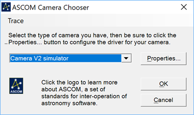
Select the appropriate camera driver in the dropdown list of the “ASCOM Camera Chooser” and click the “OK” button to confirm.
If your camera is not available in the “ASCOM Camera Chooser” it means that there is no ASCOM driver for your camera installed on your computer. To remedy this, find and install the ASCOM driver compatible with your camera. Usually the ASCOM driver can be downloaded from your camera manufacturer’s Web site but if the camera manufacturer does not release a suitable ASCOM driver and your camera is supported by MaxIm DL then you can configure SkyGuard to connect the imager camera through MaxIm DL.
 To connect SkyGuard to MaxIm DL you must set the camera control option through MaxIm DL, MaxIm DL version 5 or 6 must have been previously installed and licensed and the camera must have been properly configured in MaxIm DL camera control panel.
If your camera is not available among the MaxIm DL cameras, contact the camera manufacturer.
When camera control goes through MaxIm DL you must click the button in order to import camera settings from MaxIm DL.
When Continuous update camera state check box is checked the state returned by the ASCOM camera driver is continuously read out by SkyGuard and displayed in real time in the camera status field of the advanced user interface.
The camera timeout allows to configure how much seconds SkyGuard will wait to get an answer from the camera ASCOM driver. An error is raised when the answer from the camera exceed the given number of seconds.
To configure SkyGuard to automatically do a dithering move when the imager camera is not exposing, you must check the Enable auto dithering option.
SkyGuard expose an API (Application Programming Interface) that allows external software to trigger dithering moves. Nevertheless, the usage of the API requires an add on in the external software. We are currently working with the leading software manufacturers in order to convince and to help them to implement our API as an add on of their software. Meanwhile, the option such as the auto dithering gives SkyGuard the ability to work with external software without API implementation.
Filter wheel allows configuration of the imager camera filter wheel, which is optional. Click the button.

Select the appropriate filter wheel driver in the dropdown list of the “ASCOM FilterWheel Chooser” and click the “OK” button to confirm.
If your filter wheel is not available in the “ASCOM FilterWheel Chooser” it means that there is no ASCOM driver for your filter wheel installed on your computer. To remedy this, find and install the ASCOM driver compatible with your filter wheel. Usually the ASCOM driver can be downloaded from your filter wheel manufacturer’s Web site but if the filter wheel manufacturer does not release a suitable ASCOM driver and your filter wheel is supported by MaxIm DL then you can configure SkyGuard to connect the filter wheel through MaxIm DL.
When filter wheel control goes through MaxIm DL, you must click the button in order to import the list of filters configured in the filter wheel from MaxIm DL.
When filter wheel control goes through SGP API, you must click the button in order to define the URL and the name of filters configured in the filter wheel in Sequence Generator Pro.
By default, the URL is set to localhost on port 59590
If SGP is configured to listen on another IP port, you must edit the port number in the URL.
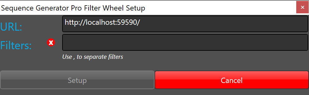
As SGP API only share the index of the selected filter, the list of all filters in the order as they have been mounted in the filter wheel must be entered manually
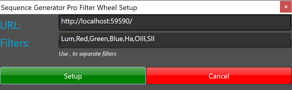
To define a 7 positions filter wheel with the following filters for each position, you must type the following text "Lum,Red,Green,Blue,Ha,OIII,SII)
|
Filter name |
Position |
|
Luminance |
0 |
|
Red |
1 |
|
Green |
2 |
|
Blue |
3 |
|
Ha |
4 |
|
OIII |
5 |
|
SII |
6 |
Click "Setup" button to confirm the configuration
Configure guiding settings
This section is very important, because it allows to define the basic guiding settings such as the guiding algorithm, guider camera driver, pixel size, Max ADU, the guider output, control and relay options.
Guiding must be carefully configured to work with your hardware in a proper way.
Guider output allows to define how the guider camera will be connected to SkyGuard. It can be connected to the guider camera through ASCOM driver, to the guider camera through MaxIm DL and to the imager camera configured in SkyGuard.
By default, it goes through ASCOM driver.
Guider output through imager camera option allows to achieve auto-guiding without guiding camera. When this option is selected the full frame guiding algorithms are processed on the long exposure raw image and the correction are calculated and sent to the mount between each long exposure.
The performances of auto-guiding through main imager camera is relative to the performance of the mount, the quality of its polar alignment, the exposure time and the focal length. As auto-guiding correction are only calculated and sent to the mount between long exposure you must find the exposure time that fit the performances of your mount, your polar alignment and you focal length otherwise you will get elongated stars.
Camera allows configuration of the guider camera. Click the button.
Select the appropriate camera driver in the dropdown list of the “ASCOM Camera Chooser” and click the “OK” button to confirm.
If your camera is not available in the “ASCOM Camera Chooser” it means that there is no ASCOM driver for your camera installed on your computer. To remedy this, find and install the ASCOM driver compatible with your camera. Usually the ASCOM driver can be downloaded from your camera manufacturer’s Web site but if the camera manufacturer does not release a suitable ASCOM driver and your camera is supported by MaxIm DL then you can configure SkyGuard to connect the guider camera through MaxIm DL.
To connect SkyGuard to MaxIm DL you must set the camera control option through MaxIm DL, MaxIm DL version 5 or 6 must have been previously installed and licensed and the camera must have been properly configured in MaxIm DL camera control panel.
If your camera is not available among the MaxIm DL cameras, contact the camera manufacturer.
When camera control goes through MaxIm DL you must click the button in order to import camera settings from MaxIm DL.
 The ASCOM connection is the preferred choice when possible because the connection through ASCOM is usually faster than the connection through MaxIm DL. So, if you have an ASCOM driver for your camera use it instead of MaxIm DL.
If the driver does not offer a HUB you may consider the OPTEC ASCOM server
Try to reconnect ASCOM guider camera after failure allows to enable/disable the attempt to reconnect the ASCOM camera after a failure in the exposure loop. This option is useful to try to recover after a USB failure.
Do not enable this option with ZWO camera because after reconnection the camera become unstable and finally hang.
Pixel size allows to define the size of the guider camera pixel in microns.
Max ADU allows to define how deep are the pixel wells of the guider camera.
With guider output through ASCOM, the pixel size and max ADU are generally automatically loaded from the driver but it may happen that the driver does not implement those properties. In this case, you must enter them manually.
Guider control allows to define by which system the guiding operation will be done. It be done through MaxIm DL or through SkySurveyor.
When the guider control is configured through SkySurveyor, the system will guide your telescope mount by using the full frame algorithm integrated into SkySurveyor suite. This means that the guiding is done on the entire guider camera frame. If guider output is set through MaxIm DL. MaxIm DL is only used to capture light from the guider camera and the tracking algorithm of MaxIm DL is not used. With SkyGuide you must set the guider control through SkySurveyor.
When the guider control is configured through MaxIm DL, the system will guide your telescope mount by using the tracking algorithm integrated into MaxIm DL. This means that only one guide star will be used for guiding. Guider control through MaxIm DL does not work with guider output through ASCOM and is not working with SkyGuide, this options is reserved for higher license level such as SkyGuard and SkySurveyor
It is necessary to define through which relay the guider correction is output to the mount.
If guider relay “Through Camera” is selected, then the auto-guider output goes through the guider camera.
In this configuration, the guider camera must be connected to the telescope mount through a ST-4 cable.
If guider output is set through MaxIm DL the auto/guider output goes through MaxIm DL.
MaxIm DL sends the auto-guider output to the relay defined by the “Settings” button in the “Guide” tab of the camera control panel.
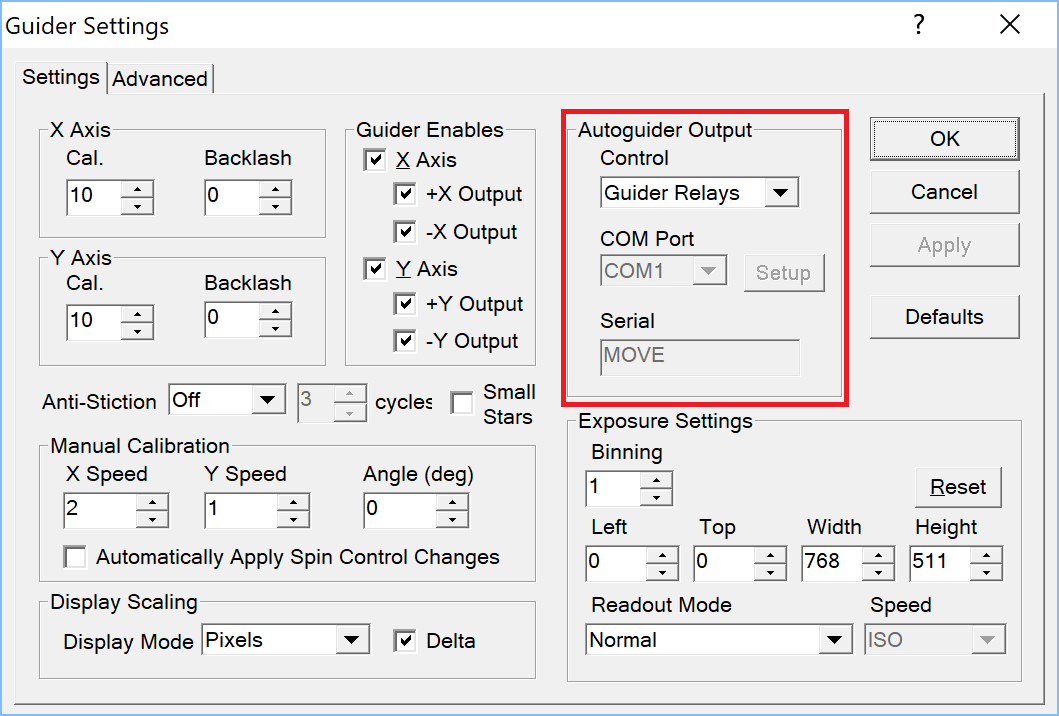
If guider relay “Through Telescope” is selected, then the auto-guider output goes directly to the telescope mount through the ASCOM driver.
Telescope ASCOM driver must support pulse guide, some drivers requires a specific configuration to support pulse guide. Please refer to the telescope manufacturer documentation to learn how to configure it. If pulse guide does not work or if it has been disabled, SkyGuard will not be able to move the telescope mount and the guider calibration will not be possible at all.
Force pulse guide allows to force the use of pulse guides on ASCOM drivers that does not support pulse guide but despite of all the pulse guide is working (when CanPulseGuide return false but PulseGuide method is working).
When guider output is set ”Through MaxIm DL”, guider control is set “Through MaxIm DL” and the guider relay is set “Through Telescope”, then the SkySurveyor full frame algorithm is used for guiding and the auto-guider output goes through the telescope ASCOM driver. The main advantage of this configuration is that the MaxIm DL legacy tracking algorithm is used on a single guide star but the auto-guider outputs in MaxIm DL are disabled and the auto-guiding is done by the full frame algorithm integrated in SkySurveyor. The main advantage of this configuration is that third-party software that remotely automate MaxIm DL can take advantage of the full frame guiding and focusing algorithms without knowing them and without requiring any modifications.
If guider relay "Through GPUSB" is selected, then the auto-guider output goes directly to the telescope mount through the ST-4 cable connected to the following GPUSB Shoestring Astronomy device:
SkyGuard send pulse guides to GPUSB through an ASCOM driver. Before using GPUSB with SkyGuard, the GPUSB ASCOM driver must be downloaded and installed via the following link : http://www.store.shoestringastronomy.com/downloads.htm
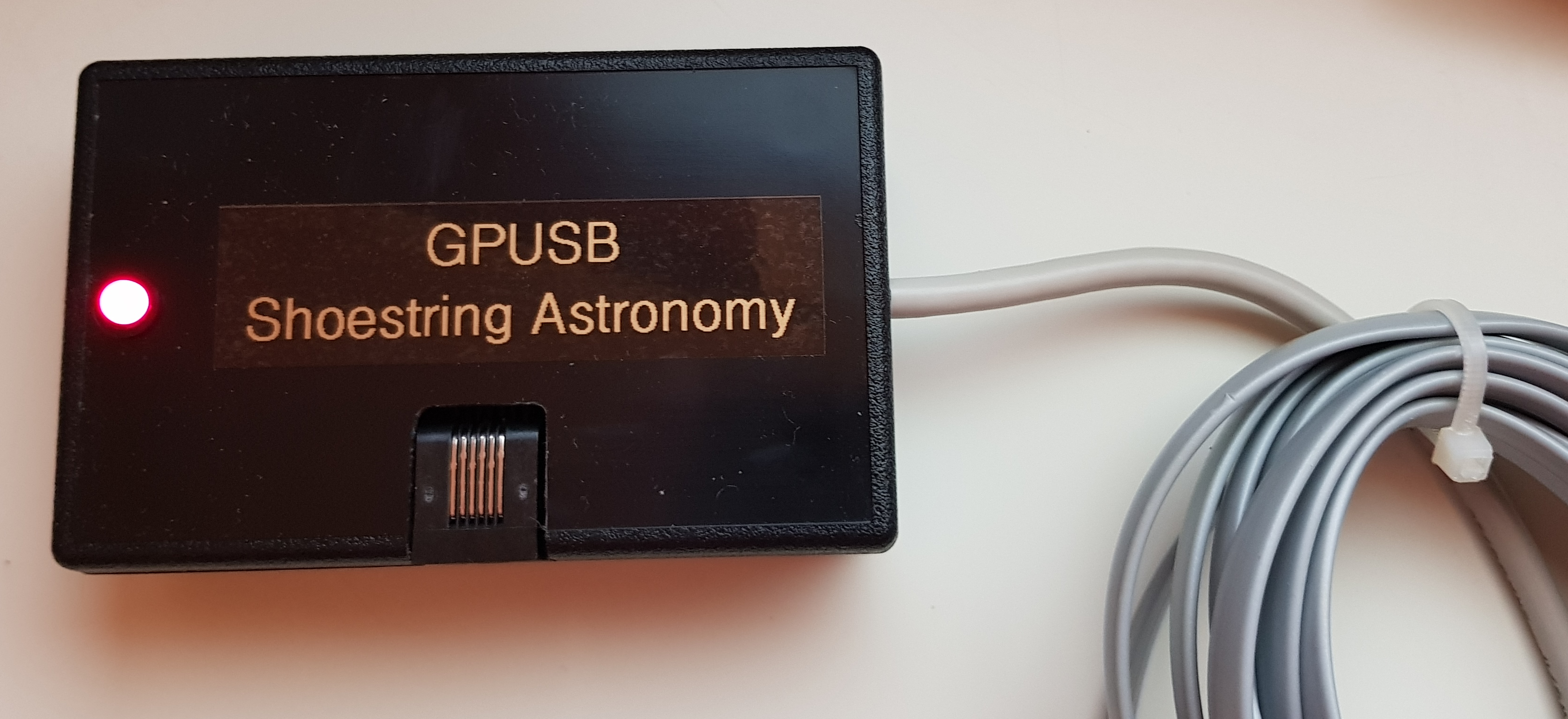
GPUSB does not work with 64bit release of SkyGuard. To use GPUSB with SkyGuard, please install the 32bit release.
To work full ASCOM, without using MaxIm DL, the imager camera and guider output must be through ASCOM.
Select an algorithm in the available algorithms dropdown list.
Restore factory default settings, if you want to restore all the algorithm settings to their default values.
Click the  button.
Once clicked, the following message appears:
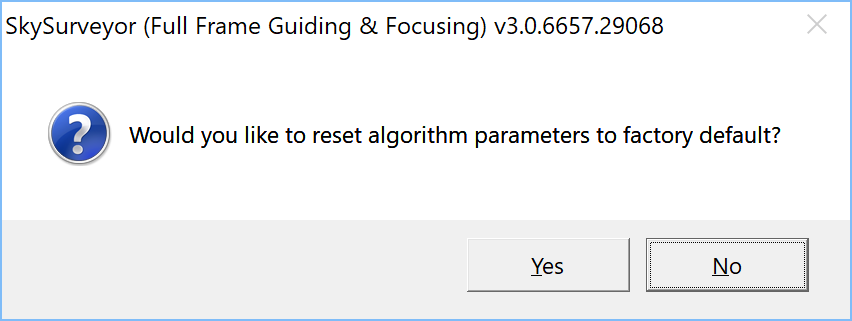
Click “Yes” to reset and “No” to cancel.
To prevent a mistake, the following confirmation message appears:
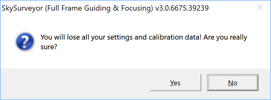
Click “Yes” to reset and “No” to cancel.
Once all parameters have been restored to their default values, the following message appears:
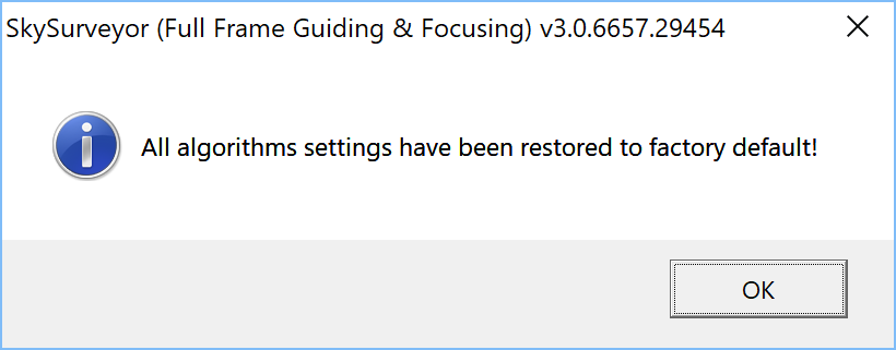
Click “Ok” to continue.
By default the right ascension axis is X. Please check your mount to ensure that the right ascension is really the X axis because otherwise the guiding will diverge after the pier flip.
Once all settings are correctly configured, the instrument can be enabled.
Enabling an instrument means that it becomes available for guiding
To enable/disable an instrument, click the check box at the left of the instrument name in the available instrument list box:

For setting up more than one instruments and advanced options see setup instruments.