Current image and head up display
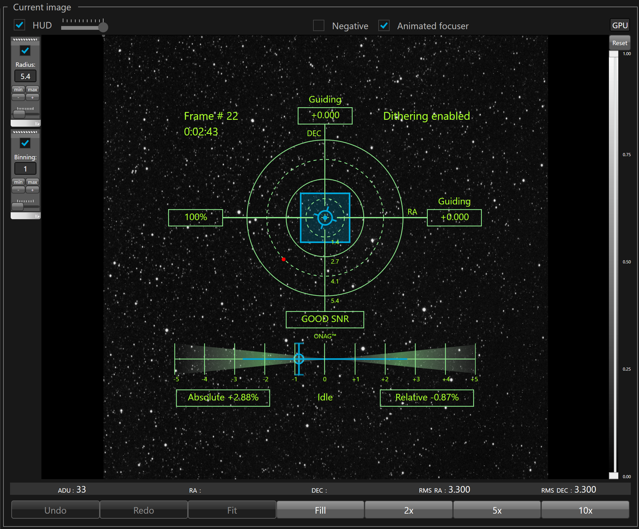
The current image panel (SKG standard GUI), is divided in 6 zones:
1. Check boxes and slider that allow to show/hide and control the transparency of the head up display (HUD). The negative check box allows to inverse the current image (background in white, and bright objects and stars black)
2. Left vertical toolbars containing HUD guiding target display scale adjustment and the option to display pixel FOV superimposed and its binning setting.
3. The current image output by the guiding camera
4. The level bar with the low/high stretch sliders and a button that resets the sliders to their maximum values
5. The information about the current image (ADU, RA and DEC position of the mouse pointer, RA and DEC RMS values)
6. Zoom command buttons
To control the transparency of the head up display, just left click, hold the left button down and move to the left to make it more transparent and to the right to make it less transparent.
To display the ADU value of a selected pixel in the image, just left click the image on the selected pixel.
To zoom in/out just use the mouse wheel or use the Fill, 2x, 5x or 10x command buttons.
To pan the zoom image, just left click, hold the left button down and move the mouse to the direction you want to pan.
To fit the image inside the view port, click the Fit button.
To restore the previous zoom, click the Undo button.
To restore the next zoom, click the Redo button.
To stretch the image, just click on the left button to the low/high slider, hold the left button down and move it to the desired level
To restore the stretch to the maximum levels, just click the "Max" button
The HUD displays the following information:
- In the upper left corner, a label shows the number of the last guider frame displayed in the view port
- In the left box of the horizontal axis, the ADIC correlation level of the current frame vs the reference frame (between 0% and 100%)
- In the bottom box of the vertical axis DEC, the Signal-To-Noise evaluation (None, Poor, Fair, Good, Excellent)
- In the top box of the vertical axis, the error on the DEC axis of the guider camera. Above the error, the label display "Guiding" when SKG is sending corrections to the guider relay and "Idle" when the correction has been disabled for this axis, including the min and max moves.
- In the right box of the horizontal axis, the error on the RA axis of the guider camera. Above the error, the label display "Guiding" when SKG is sending correction to the guider relay and "Idle" when the correction has been disabled for this axis,, including the min and max moves.
- When dithering is enabled or in progress a label shows the its status in the upper right corner.
- Below the Signal-To-Noise evaluation, the auto-focus is displayed as two scales starting from the center at 0. These scales represents the relative roundness of the astigmatism caused by the ONAG when the IR light is crossing the beam splitter.
- The blue circle crossed by a vertical line and two horizontal lines on both extremities represent the current relative roundness.
 When displayed in red, that means the current relative roundness is beyond the scale bar.
- The blue horizontal line centered in the scales represent the size of the critical focus zone. When the current relative roundness is inside the blue line that means the instrument is within its critical focus zone. When it is outside the blue line the instrument is intra or extra focal.
 The length of the blue line can only be calculated after a successful regular focuser calibration. If the calibrated system gain is empty the blue line does not appear.
 In the lower left box, a label shows the absolute roundness in percent
- In the lower right box, a label shows the relative roundness in percent.
If average roundness checkbox is checked in the focusing settings, the average values are used. Otherwise the roundness of the last frame is used.
- In the lower middle, a label shows "Focusing" when SKG is sending corrections to the focuser relay and "Idle" when the correction has been disabled, including stop gap.
The current RA and DEC errors are displayed by a rotating blue circle with spikes. When the RA and DEC errors are close to zero, this blue circle is centered with the bull's-eye, while it moves away from from it, according the amount of error measured by SKG, otherwise.
When displayed in red, that means the current RA and DEC errors are beyond the target scale.
The scale is materialized by 4 circles, the outer circle represent 100% of the scale, the inner circle represent 25% of the scale, the second circle from the center represent 50% and the third circle from the center represent 75%.
The value for each circle are displayed beside the bottom vertical axis. The value is in the unit selected from the guiding settings.
The scale can be adjusted manually with the following toolbar:
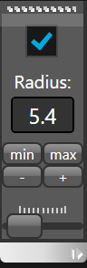
- The check box allows to enable/disable manual scale adjustment.
When disabled (unchecked) the scale is automatically adjusted to fit the errors peaks on both axis.
- The radius is displayed in the unit selected from the guiding settings
- The "min" button allows to set the radius to the minimum value
- The "max" button allows to set the radius to the maximum value (tracking window limit)
- The "-" button allows to slightly decrease the scale
- The "+" button allows to slightly increase the scale
- The scroll bar bellow allows to freely adjust the radius
The history of the guiding errors are materialized by dots. This is a scatter plot with blue and red dots. The blue dot shows errors that are below the pixel guider FOV, including binning, while the red dots shows the errors that are above the guider pixel FOV.
You can also visualize the pixel FOV superimposed to the guiding target.
To display it, you must check the box bellow and select the binning currently defined for the imager camera.
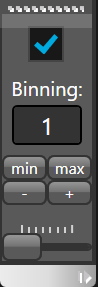
- The check box allows to enable/disable display of the pixel FOV
- The "min" button allows to set the radius to the minimum binning
- The "max" button allows to set the radius to the maximum binning
- The "-" button allows to increase the binning by one
- The "+" button allows to decrease the binning by one
- The scroll bar bellow allows to freely adjust the binning