Guiding
Before start guiding, just take a look at all guiding settings that are grouped in the following guiding group box:
 Excepted for the tracking window size all other settings can be modified while guiding.
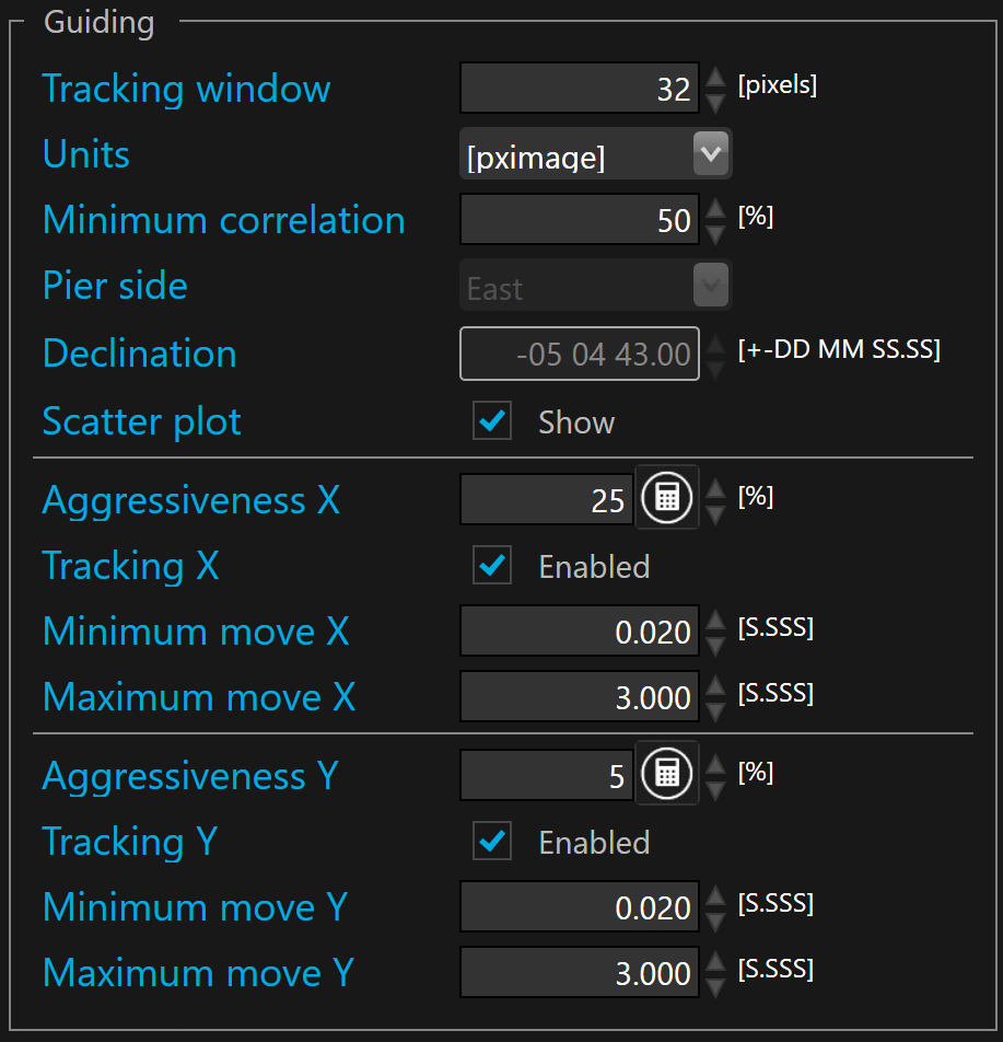
 The tracking window is defined in pixels. By default the tracking window is set to 32 pixels. SkyGuard tracks the correlation peak between the current frame and the reference one. This is an innovative approach because unlike centroid of a single star the whole guider frame is correlated with the whole reference frame and the result of this correlation generate a peak that is supposed to be perfectly centered when there is no registration (or rotation) between the current guider frame and the reference.
To analyze any motion, SkyGuard crops the correlation peak area by the size of the tracking window to save computing time.
Unlike with centroid based auto-guiding software you can freely adjust the tracking window but larger tracking window will slow down auto-guiding performances (longer processing time) while smaller tracking window will increase the risk of loosing the correlation peak in case of large move while guiding.
The units field decides in which unit the tracking and guiding errors will be displayed in the HUD, advanced GUI information, and in the plots. There is two choice : (binned) guider pixel image and arc-second.
Minimum correlation allows to define the minimum value before suspending guiding. By default the minimum correlation is 50%.
 This minimum allows to automatically suspend the guiding, for instance, when a cloud is passing through the guider camera field.
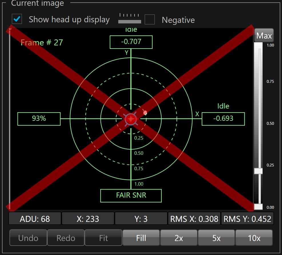
When correlation is below the minimum, a red cross is displayed on the HUD
Pier side shows the current side of the equatorial mount. When SKG is connected to a telescope ASCOM driver, this parameter value is automatically updated by the ASCOM driver and it cannot be modified manually.
 Auto-guiding use the pier side to know if the pulse guide direction must be reversed on the RA axis. When SKG is not connected to a telescope ASCOM driver, one must set the pier side manually. If the pier side does not match the actual pier side of your equatorial mount, the corrective pulses on RA axis may move the telescope away from the target instead of maintaining it on the target and the captured image will have elongated stars.
Declination shows the declination of the current target pointed by the telescope. When SKG is connected to a telescope ASCOM driver, this parameter value is automatically updated by the ASCOM driver and it cannot be modified manually.
Auto-guiding use the declination to adjust the RA pulse duration (magnitude of the RA correction) according to the declination. When SKG is not connected to a telescope ASCOM driver, one must enter the target declination manually. If the declination does not match the target DEC pointed by the telescope, the corrective pulses on RA axis may move the telescope in a heretic and unstable way leading to elongated stars
Show scatter plot provides a visual feedback about guiding and its history in the HUD. By default the scatter plot is shown.
Aggressiveness allows to define the hysteresis of the auto-guider. It can be defined differently for X and Y axes. The default value for X (RA) is 25% and 5% for Y (DEC).
SKG offers a tool that allows to automatically calculate the optimal aggressiveness on each axis for your setup and your local observatory conditions. Too short guider exposure values and too large aggressiveness values are a common source of poor guiding and elongated star, especially under seeing limited conditions.
To calculate optional value you must press the  button.
Enable tracking axis enables/disables corrections for the concerned axis. It can be configured independently for each axis. By default both axis are enabled.
Minimum move (per axis) sets a lower limit for sending corrective pulses to the mount. If the corrective pulse duration is lower than the minimum duration, the pulse will not be sent. It can be configured differently for both X and Y axes. By default the minimum duration is set to 0.020 second.
To disable minimum duration, you must clear the value (empty).
Maximum move (per axis) sets a upper limit for the duration of a corrective pulse. If the corrective pulse duration is greater than the maximum duration, the maximum duration is used. It can be configured differently for both X and Y axes. By default the maximum duration is set to 3.000 second.
To disable maximum duration, you must clear the value (empty).
Start guiding
Once the guider frame acquisition has started, guiding can be started.
To start guiding, click the  button.
If the guider is not calibrated the start guiding button is disabled.
The check box at left side of the button allows enabling/disabling the start guiding operation automatically at the same time one starts exposing (SKG acquisition loop). By default disabled.
Stop guiding
To stop guiding, you can either click  or
or  or
or  buttons.
Stopping the guider exposure or disconnecting the instrument will result of taking a new reference image when one resumes.
Stopping guiding only suspend auto-guiding when resume the current reference frame is still on use.