Information
The information panel shows the status of the acquisition loop and all statistics about the guider output frames, current and refrence.
Statistical information are organized in two columns : the first column is relative to the current guider camera output frame and the second, is relative to the guider reference frame automatically taken when the guiding loop is started.
 Reference statistic fields remains empty when the guiding loop has not yet been started and reset when the guiding loop is stopped and restarted and when the camera is disconnected.
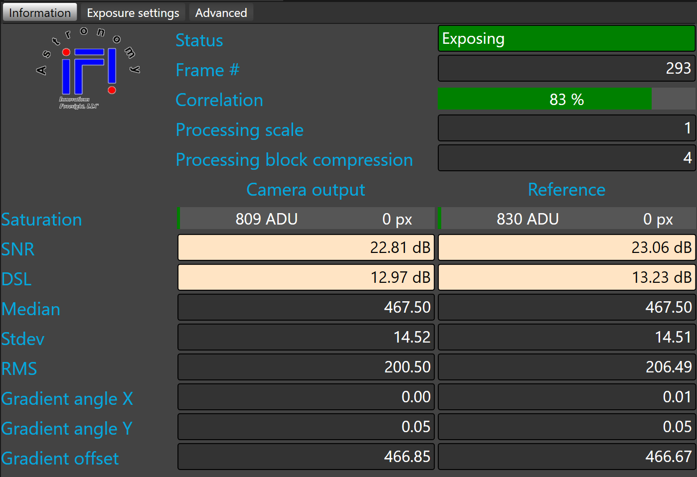
Status shows the current status of the acquisition loop, the following statuses are available:
|
Status |
Description |
|
Idle |
Guider camera is not connected or acquisition loop is not running. |
|
Exposing |
Guider camera is exposing. |
|
Processing |
Acquisition loop is processing the guider output frame. |
|
Saving |
Acquisition loop is saving the guider output frame.
|
|
Waiting |
Acquisition loop is waiting on the delay defined in exposure settings tab |
|
Waiting for guiding |
Acquisition loop is waiting on the guiding loop before starting a new exposure. |
|
Paused |
Acquisition loop has been paused. |
|
Failed |
A failure occurred in the acquisition loop (check SkyGuard.log to get more information about the failure). |
|
Moving guider |
Acquisition loop is sending pulse to the mount through the relay. |
|
Suspended while telescope is not tracking |
Acquisition loop is suspended while the telescope is not tracking (or slewing)
|
|
No changes waiting next guider frame |
There was no change detected between the current guider frame and the previous guider frame.
|
Frame number shows the number of guider output frames that was captured by the acquisition loop.
This number is reset when the acquisition loop is stopped and restarted and when the camera is disconnected.
Correlation shows the percentage of correlation (0% to 100%) between the current guider camera output frame and the guider reference frame.
This field remains empty when the guiding loop has not yet been started or if the reference frame has not yet been captured or in case that the reference has been reset.
 The main purpose of the correlation is to measure if a cloud or anything else is dimming the guider camera FOV, in order to automatically suspend guiding when the correlation goes below a given threshold.
It may also happen with too low SNR values.
Processing scale shows the scaling factor used by the SKG algorithm for processing the frame (eventually binned by the user).
Processing block compression shows the the block compression factor used by the SKG algorithm for processing the frame..
 Based on raw image size, user binning, local seeing, focal length, camera pixel size SKG, by default, automatically adjusts the scale and the block compression values to provide optimal processing performances. We recommend to use the automatic mode.
If needed these parameters can be manually set from advanced settings
Saturation shows the value of the highest pixel in the guider frame in ADU as well as the number of saturated pixels (pixel that reach the maximum ADU of the guider camera)
 Avoid saturated pixels as much as possible to do so you may reduce the guider frame exposure time.
However it is not recommend to use too short guider exposure values under seeing limited condition. In mos conditions one wants to use at least 3 seconds.
SNR shows the Signal-to-Noise ratio in dB. The signal rms value against the noise rms floor.
DSL shows the dynamic range ratio in dB. The signal rms value against the useful minimum statistical signal level for a given probability level.
|
<15 dB |
Poor |
Guiding may still be possible but they could be an occasional signal loss or some erratic moves depending of the correlation threshold selected. |
|
>=15 and <25 dB |
Fair |
Guiding should be possible without any major interruption. Noise could be a limiting factor |
|
>=25 and <35 dB |
Good |
Guiding should be nominal. Limited by the seeing. |
|
>35 dB |
Excellent |
Guiding should excellent . Limited by the seeing |
Median, Standard deviation (StDev), and root mean square (RMS) are calculated on the processed guider frame. The values are displayed is ADU.
Statistics are useful to adjust the noise rejection. In case of low SNR or low noise, one could lower the rejection probability percentage and/or the associated weight for minimizing signal loss.
Gradient angles X and Y shows the angle of the gradient detected in the guider frame. The values are displayed in degrees.
Gradient offset shows the bias (DC) of the gradient in ADU.
Correlation is sensitive strongly to a strong gradient. If soe gradient remain SKG may not work correctly and one may experience strange correlation shape. The gradient is effectively canceled by the two pre-process filters but you must ensure that there is at least one configured.
Both can also be enabled together if facing a very strong gradient at the expense of some extra computing power.
A typical situation with a possible strong gradient may arise from the shadow (vignetting) of some part of the optical train when using an off axis guiding approach.