Why could I see through my ONAG?
Although the ONAG dichroic beam splitter (DBS) reflects 98%, or more, of the visible light, the few percents left allows to see through when looking at a bright source, like day light.
Also without a scope to focus the beam, light comes from many different angles. The DBS cut-off wavelengths chages with the arrival angle of incidence of a ray.
The total result of those effects can be seen because the human eye is a very sensitive receiver.
From the ONAG imager port the reflected light seems colorized, is this normal?
The ONAG dichroic beam splitter (DBS) uses a multi-coating interferencial technology.
Like anti-reflection (AR) for lenses and optical surfaces it exhibits changing colors, function of the light incidence angle.
The DBS is optimized for a 45 degree reflection angle, which is its working nominal condition.
In astronomical applications light beams have a very little divergence, 1 to 2 degrees at most. Under those conditions the DBS acts like any normal mirror would.
However when you look at the ONAG alone, “naked eye”, on the open you are very far from this nominal condition. Diffused illuminations, such as day light scenes, and absence of any optical element to focus the beam, will result in a wide reflection angles leading to noticeable color variations.
What is the best procedure to focus a guide star?
The ONAG guider port has a built-in focuser, with an effective travel of about 9mm (~1/3″). Its allows you to fine focus the guide star without disturbing your imager focus point, or involving your scope focuser mechanism.
First be sure you have selected the right extension tube (spacer) combination for your set-up, by considering both imager and guider back-focus (including any other element, such as a filter wheel). Please refer to the ONAG user manual for further information
When you move the ONAG guider focuser all the way, the guide star should change form from a vertical ellipsoidal shape to a horizontal ellipsoidal shape, or the opposite in function of your CCD reference frame position. The optimal focus point is achieved when both ellipsoid collapse becoming a spot, or a little cross. This is normal and not a source of concern. This feature becomes handy when manually seeking for best focus, or while using our real time autofocus solution, SharpLock.
Since most scopes and optical components are not optimized for the near infrared (NIR) there is maybe small distortion involved.
Autoguider algorithms are mainly based on centroid algorithms and are not sensitive to this. They average pixels from the all guide star area, so the maximum pixel value or FWHM are not much relevant in this case, unlike for imaging.
If you use computer assisted focusing software the right figure of merit should be the half flux diameter (HFD), or ½ FD. The half-flux diameter is the diameter in pixels that contains half the energy in a star image. In other words, if you add up the pixel values (less the background) inside the diameter, and outside the diameter, you will get the same number. This measurement gives a very similar answer to FWHM, but it is much more robust in the presence of seeing, noise, and can handle non circular distorted images, even out-of-focus like “donuts”. The HFD varies linearly with focus position making it reliable to locate the best focus regardless the star shape.
If you use guiding software reporting the SNR level, watch its value, you should seek for its maximum. If you do not use any software, the best focus will be achieved when the guide star cross like shape is minimized and symmetric.
The two images below show the same guide star seen from the imager (the first one), or from the guider (the second one), at best focus, same camera, set-up, and cropping.
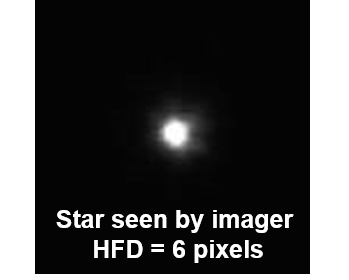
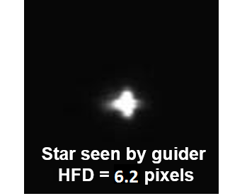
The cross like shape of the guide star viewed from the GP is clearly visible. Yet as far as the energy budget is concerned both cases have almost the same HFD.
When you reached the desired focus, hand tighten the ONAG focuser screw to avoid any motion or flexure.
How should I clean the ONAG dichroic beam splitter (mirror)?
The ONAG DBS is a high quality multi-coating optical element and must be handle with care as such.
Should you need to clean it, first remove any dust, or other large particles, using either optical grade compressed air, or an optical grade brush.
In any case do it very gently. As a general rule, touching the DBS surface as little as possible.
If you have to do it use an optical multi-coating cleaning solution (available from many sources), never apply it directly to the surface, use a lens tissue.
We do recommend to wear disposable latex glove for the task. Always apply the minimum amount of pressure and force when cleaning the DBS surface.
How to minimize flexure?
The ONAG is designed to avoid flexure, using the same scope and optical train than your imager.
Be sure that the guider focuser and the X/Y stage nylon screws are hand tightened before starting any astrophotography session.
Avoid using extension tubes, spacers, with a total length exceeding few inches for the guider as much as possible.
Good cable management is important for good telephotography to avoid pulling any cameras, or other equipments, in the course of the mount motion.
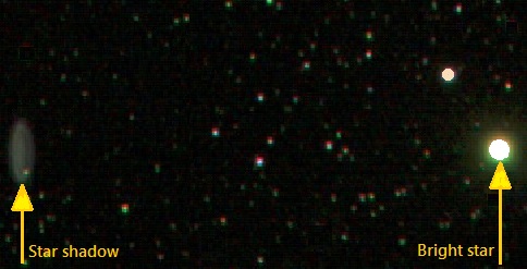
I see dim 'donut' shape like ghost images near bright stars. what is this and what to do to eliminate it?
The ONAG dichroic beam splitter (DBS) is fully multi-coated, including a wide range anti-reflection (AR) coating on its back. However if you well over expose stars, saturating (clipping) your imager sensor, a very small fraction of the near infrared (NIR) light reflected back could show up as very dim “donut” like shape few millimeters away from its actual location on your imager CCD. This refection is out of focus with some astigmatism.
Below a typrical example of such ghost image:
 Credit: Knox Worde
This is no different than other stray reflections you may experience in any optical systems, even with proper AR coating, if you work with light levels way in excess to your sensor saturation (clipping) point.
Chance is you may have a CCD blooming problem way before you would ever see such reflections.
Should you experience the problem anyway, be sure your imager has a NIR blocking filter.
Most , if not all, one shop color cameras and DSLR do. If you work with a filter wheel and a monochrome camera, this should be taken care by your LRGB filter set.
However be aware there are out there RGB filters without, or poor, NIR blocking feature, and even some luminance filters do not cut the NIR too (beside their specification telling otherwise).
Do not confuse clear filters with luminance filters, a common mistake.
In such case you may have to add a UV-NIR blocking filter, or use a LRGB filter set cutting UV-NIR (should cut off below 370nm, and above 700nm).
Also it is recommended to avoid clipping any star as a general good practice rule. Just doing this should avoid any ghost images.
Should you still experience such “ghost” images after following the above recommendations, feel free to contact our customer service for further investigation,we’ll be glad to help you
Can I use a focal reducer with my ONAG?
Yes you can.
Focal reducers (FR) should be at, or near, its specific distance DFR to the imager focal plane to fulfill their specifications.
However popular 0.63x reducer-correctors, such as the Meade/Celestron FR, will work fine in a range of typically +/- one inch (25.4mm) of their DFR. In such conditions the FR optical correction remains essentially untouched.
Yet deviation from the DFR will change the FR reduction factor h.
In first approximation h is given by:
h = 1-q/f
Where q is the actual distance between the FR and the imager focal plane, and f the FR’s focal length.
We also have:
q=f*(1-h)
For instance:
Celestron 0.63x focal length = 235mm
DFR = 235*(1-0.63)=87mm
If we place the reducer one inch further to the imager focal plane this leads to:
q = 87+25.4 =112.4mm and h = 1-112.4/235=0.52x
A 17% lower reduction factor h, meaning more reduction.
There are two options for placing the FR with the ONAG:
The FR can be located on front of the ONAG at its scope port (SP). In this case you need to consider the 66mm (2.6″) ONAG back focus in the calculation of q.
Alternatively the FR can be inserted between the ONAG imager port (IP) and your imager (or filter wheel if any).
In this configuration the ONAG back focus does not play any role in the calculation of the distance q.
Yet be aware that the ONAG user manual differential back focus table will not provide the correct selection for the extension tube set up anymore.
Most likely the guider camera should be moved further away from the ONAG guider port (GP).
In order to avoid large guider extension paths we offer a adjustable focal reducer (AFR) to be placed in front of your guider. This one has been optimized for near infrared (NIR) using aspheric optics. The AFR works with most FRs, including the Celestron, Meade 0.63x, 0.33x, Starizona SCT corrector, Optec, … See the ONAG user manual for further information.
The image below shows the ONAG with a Meade 0.33x FR is placed before the imager (SBIG ST4000XCM).
Here our adjustable NIR focal reducer (AFR) has been used with a Meade DSI camera for guiding.
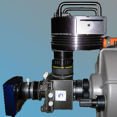
ONAG with a Meade 0.33x focal reducer and a AFR
I have an adaptive optic module. Will it work with my ONAG?
Yes it will.
Stand alone adaptive optic (AO) products, such as the ORION SteadyStar (TM), or the SXV-AO from Startlight XPress can be placed anywhere between your scope optical back and the ONAG scope port.
If you have a SBIG AO-8 adaptive optic module, we provides an AO-8 adapter plate to interface it with your ONAG, for an AO-8T please contact SBIG for a AO-8 compatible back plate.
The AO-L only suppotred by the ONAG XT classes of product.
How could I guide using the near infrared (NIR)?
Unfiltered CCD/CMOS sensors are quite sensitive in the near infrared range (NIR), above 700nm. This is why for imaging you need IR blocking filters. Most one shot color cameras have built-in UV-IR filters, while monochrome cameras do not. They rely on external filters, such as LRGB, or narrow band filters.
The amount of NIR energy received from a given star is a function of its temperature. The star’s spectrum can be found from its surface temperature using the black body radiation theory.
Let’s define the light visible range from 350nm to 750nm and the NIR range from 750nm to 900nm.
Spectral integration shows that there is 70%, or more, as much energy in the NIR range than in the visible one (as defined above).
This energy can be used for NIR guiding.
The stellar classes M, L, T are related to surface temperatures ≤3700K (red).
Stars from those classes radiate a large amount of energy in infrared. A lower star surface temperature means more NIR energy.
More than 76% of the main sequence stars belong to class M, which makes them the most common stars across the universe.
Because this, and also since the ONAG integrated X/Y stage gives access to a large FOV, there is a very high probability to find a usable guide star using NIR with the ONAG.
Also guiding in NIR offers a unique opportunity to significantly decreases the seeing effect on the guide star (star wander), which in turn improves tracking and auto-guiding.
To learn more about NIR guiding click here.
I run my equipment in automation (remote) what should I consider when using the ONAG?
The ONAG can be used in fully automated remote observatory situations.
The best solution is to guide on axis using a guiding camera with a large chip (it must be monochrome camera without any IR blocking filter).
This provides a rigid solid state solution, withou any part in motion.
Selection of a guide star is then trivial, using any guider frames.
Also saving a rotator provide extra back focus and allows reusing flat frame over and over again.
Having a large on axis FOV without any motion is the only solution for taking advantage of multi-star (constellation) guiding technology. Some software applications for astophotography provide such capability, like Maxim DL (version 6 and above).
Alternatively you could use your ONAG as you would do with an OAG. In fact the ONAG is an ON-OFF guider. In this configuration you would offset the guider camera using the integrated X/Y stage. However you do not need to be far off axis, you can remain inside you imager FOV, near your scope optical axis.
If you use a rotator be sure you can freely rotate 360 degrees without bumping to anything, this is not different than with any other equipment, such as filter wheel and cameras.
You also want to have a good cable management strategy. Avoid any guider cable traction during tracking and rotation. Beside you could lose a connection, of break something, excessive force may result in flexure of the guider assembly, such as extension tubes.
For guiding and associated software set-ups you need to consider that, unlike for an off-axis guider (OAG), the ONAG does not have any mirror (reflection) involved in the guider light path.
Therefore you should select the option “Self-Guiding”, or an equivalent one, when available.
Failure to do so will most likely lead to erratic behavior and impossibility to guide.
How to use a light pollution reduction filter with the ONAG?
Light pollution reduction filters selectively reject narrow bands associated with wavelengths from common urban skyglow, such as sodium vapor street lights.

Skyglow imaging filter transmission plot
(credit Orion Telescopes & Binocluars)
Most of them will also block UV and NIR lights (>700nm). Therefore such filter can not be placed in front of the ONAG (SP) otherwise the guider camera will not receive enough, if any, NIR light (>750nm).
The filter should be located at the ONAG’s imager port (IP) in front of the camera, usually an one shot color camera, or DSLR.
This can be achieved with a filter wheel (FW) which offers T-threaded connections.
Below an image of the ONAG associated with a 2″ ORION FW and a SBIG ST2000XCM one shot color camera. The FW is used for the light pollution reduction filter, when not needed a clear (empty) position of the FW can be selected instead.

ONAG with a 2″ ORION filter wheel for a skyglow imaging filter
An alternate option is available for some DSLRs. There are clip style filters which can be placed inside the DLSR body, before the camera mirror. This avoids the need for a FW and minimize the back focus.
For further information please visit:

There is yet another solution to place the filter between the ONAG’s IP and the imager camera without any filter wheel.
This approach will reduce the extra back focus needed for the filter to a minimum.
PreciseParts provides ONAG custom adapters for most scopes, imagers, accessories, and specific set-ups. They have our products on file.
You can order:
-1-
A generic female 2″ (48mm) filter to your imager camera specific connection (such as a female T-thread) adapter.
Then
-2-
An ONAG imaging port (IP) to generic male 2″ (48mm) filter adapter.
In both cases you would ask for a minimum adapter back focus of 5.6mm, or 0.22″ to insure clearance for the filter.
In this configuration the filter is placed in between the two adapters. This leads to a very compact and low profile solution.
Please visit:

Notice:
There are two possible choices for the filters (48mm).
Either generic, which should be used for any 2″ filter with a thread M48 x 0.75mm (excepted Celestron, Meade, and Orion brands).
Otherwise select Meade/Celestron/Orion 48mm for those suppliers, or for any 2″ filter with a M48 x 0.6mm thread.
For further information feel free to contact our customer service, I’ll be glad to help.
How much guiding error is too much?
This is a very good and important question, and its answer is fundamental for good quality images.
A simple rule of thumb is to keep the rms tracking error at, or below, the local seeing. The better the seeing the smaller the tracking error needs to be.
For further information on this topic please visit our eduction page “how much guiding error is too much?“