Disclosure:
This webpage provides support for ONAG users in their back focus calculations.
The use of any result for making any decision on the final setup and related adapters/spacers, including any purchase, is solely the responsibility of the user. Innovations Foresight cannot be held responsible, nor liable, for any consequence related to the use of the webpage, its information, its results and recommendations. We strongly advice and recommend the user, before committing to any setup decision, to review all and any results carefully as well as to draw a sketch, at scale, of the future setup including an ONAG in order to avoid any possible mechanical interference between various components (such as scope visual back, focuser, FW, …).
© Innovations Foresight 2016.
When using an ONAG® both the imaging and guiding cameras need to be parfocal. This means that when the imager is at best focus the guider too.
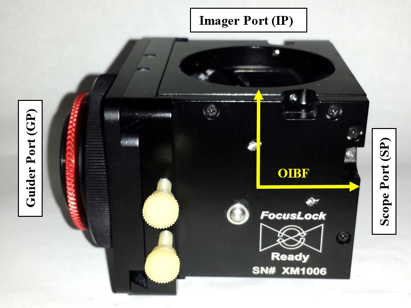
The two above pictures show the ONAG® XM (same concept for the ONAG® SC) optical ports and the optical paths for the imager and guider.
The ONAG® optical back focus distances from the SP to the IP are:
ONAG® SC: OIBF = 66+/-2mm ONAG® XM: OIBF = 68+/-2mm
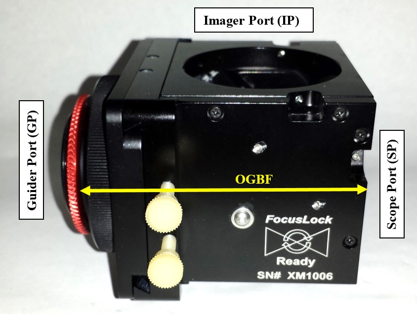
The ONAG® optical back focus distances from the SP to the GP are larger.
The values below assumed that the helical focuser GF is half extended (+4.5mm):
ONAG® SC: OGBF = 90+/-1mm ONAG® XM: OGBF = 101+/-1mm
The key value in the parfocal calculations is the differential back focus for the cameras (DBF). Its value should be eventually made equal to the ONAG® back focus offset value, or BFO. The BFO is defined as the difference between the ONAG® GP (OGBF) and the ONGA® IP (OIBF) optical back focus distances:
BFO = OGBF – OIBF
Therefore the BFO values are:
ONAG SC BFO = 24m
ONAG XM BFO = 33mm
When using our optional astigmatism corrector those values should be reduced by 3mm due to the optical effect of the corrector.
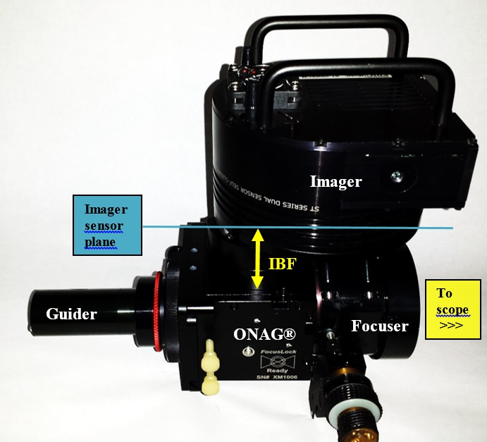

The two above pictures show the imager optical back focus distance (IBF) and the guider optical back focus distance (GBF).
The IBF is defined as the optical distance from the imager sensor plane to the ONAG® IP, which includes any spacers/adapters, filter wheel, …, in this path.
The GBF is defined as the optical distance from the guider sensor plane to the ONAG® GP, which includes any spacers/adapters, …, this path.
The DBF is defined as the difference between IBP and the GBF back focus distances:
DBF = IBF – GBF
When using our astigmatism corrector at the ONAG® guider port (GP) this DBF value should be increased by 3mm.
Should you have a focal reducer FR please see the ONAG user manual version 6, sections 8 and 9, available at our support page Document, tools and drivers.
The DBF value should come close, in a ~+/-3mm range, to the ONAG® BFO value such the integrated ONAG® helical guider focuser (HGF) can be used to fine focus the guider.
When both values, the DBF from the cameras and accessories, and the BFO from the ONGA® match the camera are then parfocal.
The HGF can deal with back focus differences up to ~+/-4mm, since it has a travel of at least 9mm.
In summary the condition for making the camera parfocal is:
DBF = BFO
From an optical train and scope point of view, the total optical back focus (TOBF), including the ONAG®, the imager, its accessories (filter wheel, spacer/adapter, …), eventually limits the scope focusing mechanism ability to reach focus. The TOBF does not include accessories before the ONAG® such as a focuser, a rotator, and/or AO unit, can be estimated with the following formula:
TOBF = IBF + OIBF
The ONAG® integrated X/Y stage requires a 14mm clearance from the top of the ONAG® body, at the Imager port (IP), for full upper vertical travel (Y). If there is interference with the imager/FW body, or any adapter, you may consider using a spacer for providing clearance. Even in the case of a limited upper Y travel the X/Y stage has still a very large guiding FOV. The lower Y vertical travel, as well as the X travel are fully available.
Most scopes, such as SCT, are designed for some optimal back focus distances, for which they reach their nominal specifications (such as focal length, F number, field of view, resolution, …). For instance the Celestron EdgeHD SCT series have a built-in corrector, and they will provide optimal performance if the focal plane is at, or near, a predefined distance from the scope visual back. For further information in this topic please visit our support page EdgeHD back focus tolerance.
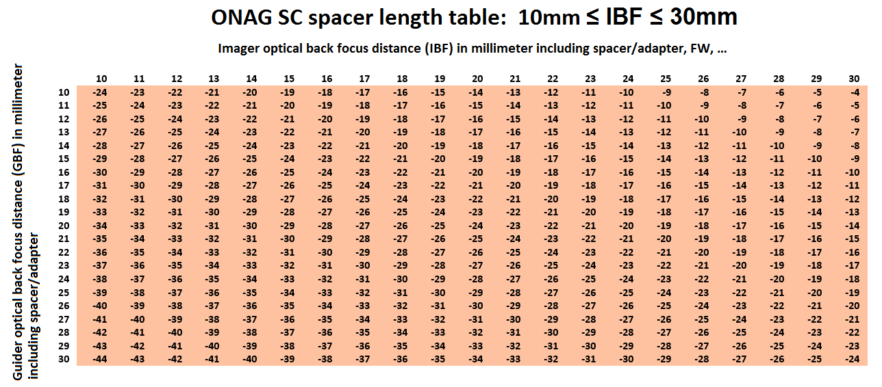
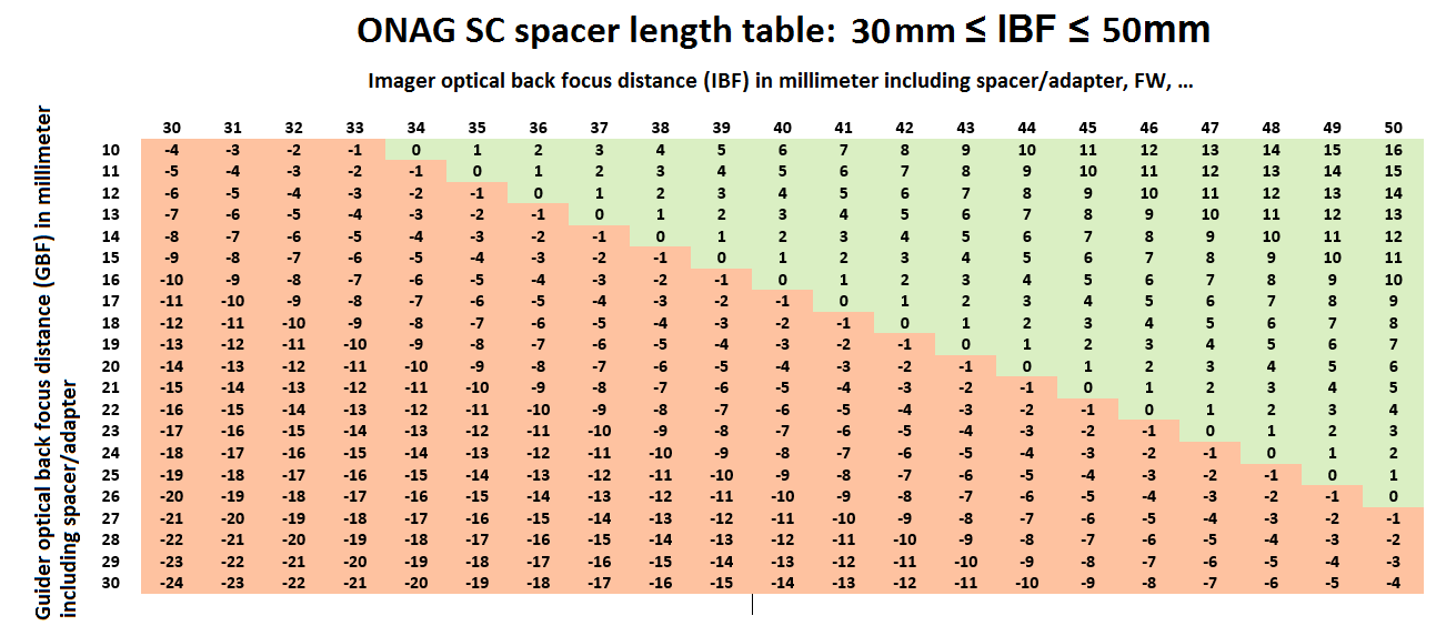
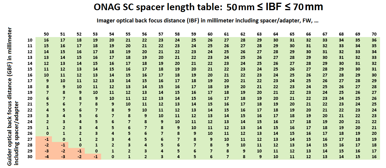
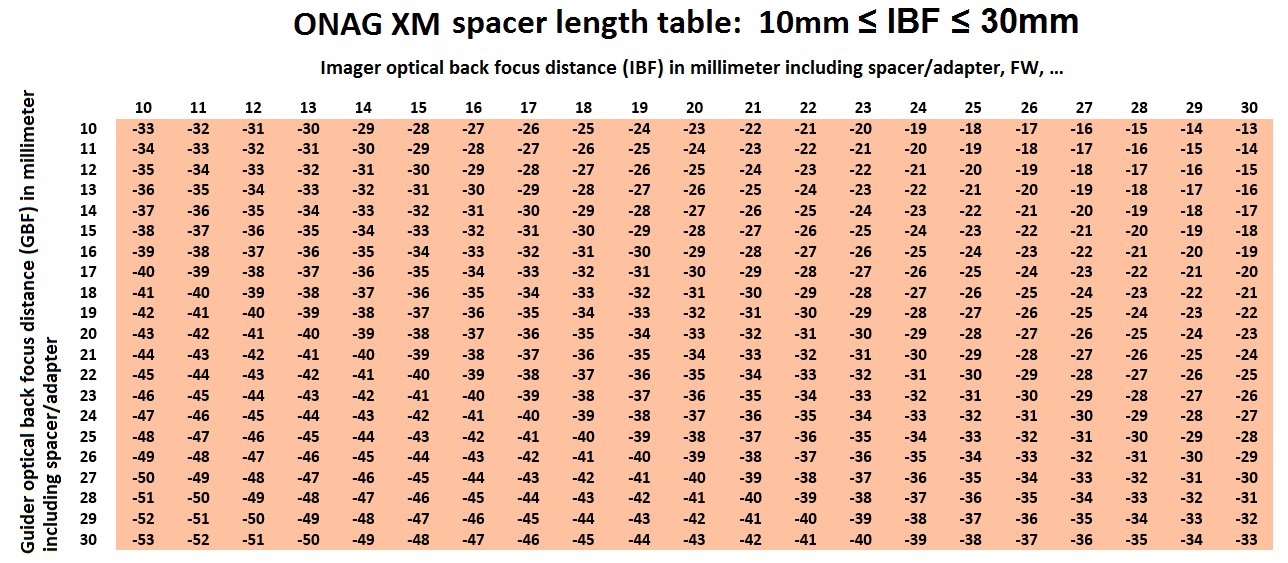
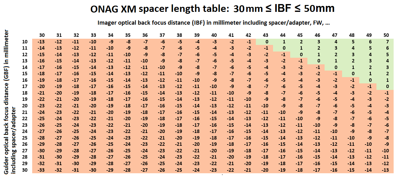
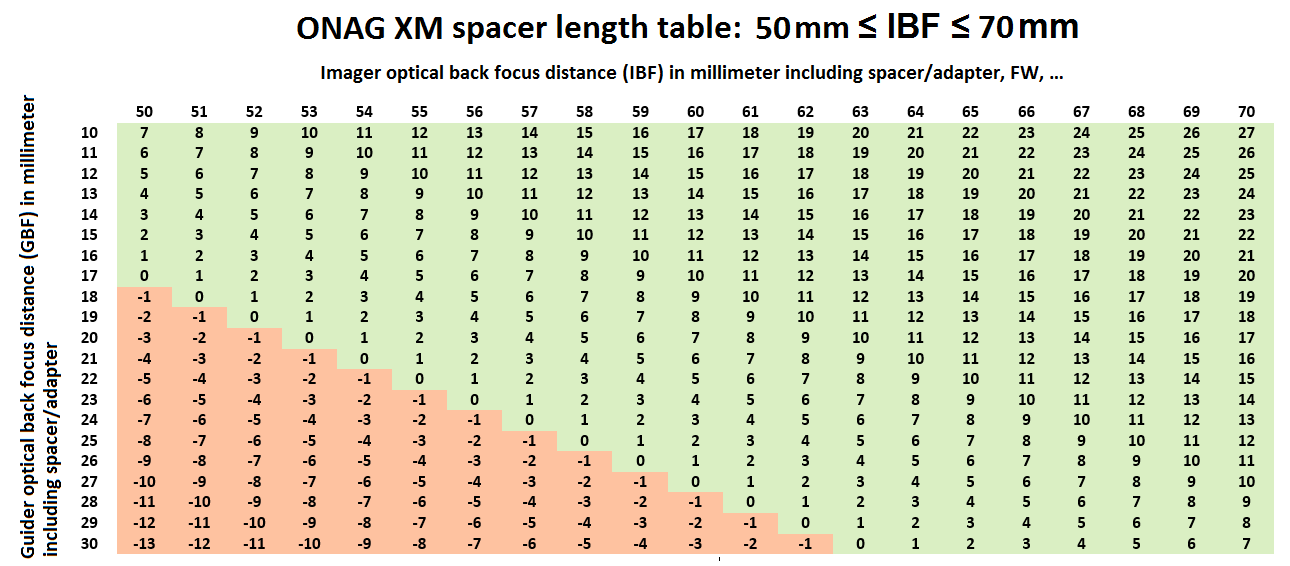
In such case you may even want to add a spacer(s) on the scope port (SP) to reach the right distance. The tables below provide the length, in millimeter, of the spacer/adapter required to make both camera parfocal versus both imager (IBF) and guider (GBF) back focus. Remember that the IBF and GBF are the total optical back focus distances, they include spacer/adapter, filters, FW, …, if any, located between the camera and the ONAG® optical ports.
A green positive number means a spacer/adapter of that length should be placed at the ONAG® guider port (GP), in front of the guider.
A red negative number means a spacer/adapter of that length (sign removed) should be placed at the ONAG® imager port (IP), in front of the imager.
Example #1 ONAG® SC:
Imager DSLR Canon EOS (EF and EF-S mounts)
Flange back focus distance = 44 mm
T-ring adapter for EF/EF-S mount back focus = 8 mm
IBF = 44 + 8 = 52 mm back focus (low profile configuration)
Notice: T-ring adapters for most cameras are designed and made to lead to a 52mm back focus distance (like here for the Canon EOS).
Guider SX lodestar (any version) optical back focus = 12.5 mm
C-to-T adapter back focus = 6.4 mm (connect to ONAG© GP T2)
GBF = 12.5 + 6.4 = 18.9mm ~ 19mm
Differential back focus DBF = 52 – 19 = +33 mm positive!
By calculation:
The ONAG® SC BFO is 24mm, therefore to be parfocal one needs a spacer at the ONAG® GP with a length of:
33 – 24 = 9mm (ONAG® helical focuser half extended).
Using the table above (IBF = 52, GBF = 19):
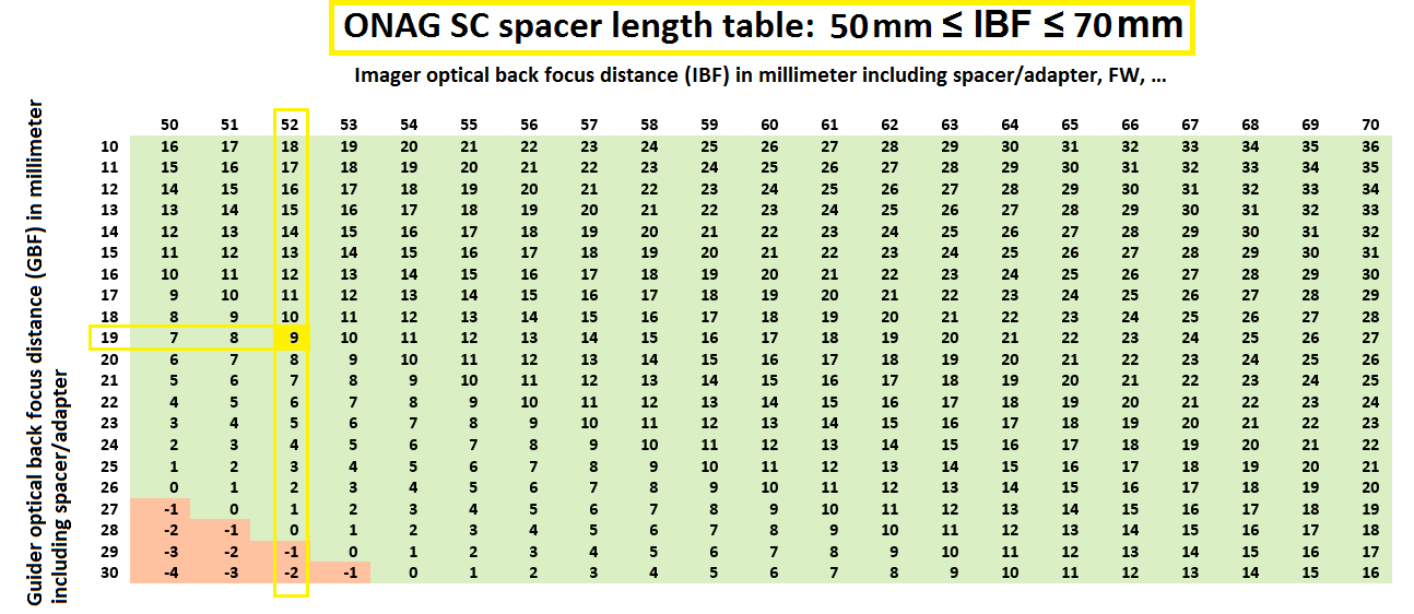
We found +9mm a positive (green) value therefore the spacer must be placed at the ONAG® GP.
The total optical back focus in this configuration is:
TOBF = IBF + OIBF = 52 + 66 = 118 mm
Be aware this configuration could prohibit access to some DSLR functions and interface, if its body is too close to the ONAG®.
To insure full motion of the upper vertical travel of the ONAG® X/Y stage we may consider adding a T2 spacer of 14mm long at the ONAG® IP to clear the DSLR body from the stage (see standard and low profile configuration below, sections 5 and 6)
In this case the IBF becomes:
IBF = 52 + 16 = 68mm
Therefore the new DBF is:
Differential back focus DBF = 68 – 19 = +49 mm positive!
To be parfocal one needs a spacer at the ONAG® GP with a length of:
49 – 24 = 25mm (ONAG® helical focuser half extended).
Try with the above table to compare.
The new total optical back focus in this configuration is:
TOBF = IBF + OIBF = 68 + 66 = 134 mm
For instance if this configuration is used with a C11/C14 EdgeHD scope you would need that the adapter/spacer connection to the scope visual back (in front of the ONAG® is 146 – 134 = 12mm long to meet the Celestron nominal back focus recommendation.
Example #2 ONAG® SC:
Imager OSC SBIG STF83000C optical back focus = 17.5 mm
IBF = 17.5 mm back focus (low profile configuration)
Guider SBIG ST-i (monochrome) optical back focus = 13.36mm
1.25” filter thread to T2 adapter back focus = 7mm (connect to GP T2)
GBF = 13.36 + 7 = 20.36mm ~ 20.4mm
Differential back focus DBF = 17.5 – 20.4 = -2.9 mm ~ -3mm negative!
By calculation:
The ONAG® SC BFO is 24mm therefore to be parfocal, since the DBF is negative, one needs a spacer at the ONAG® IP with a length of:
24 – (-3) = 27mm (ONAG® helical focuser half extended).
With a T2 27mm long spacer at the IP there is enough clearance for the camera body.
Using the table above (IBF ~ 17, GBF ~ 20):
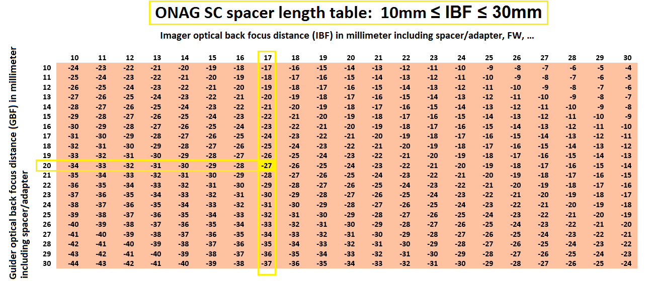
We found -27mm a negative (red) value therefore the spacer must be placed at the ONAG® IP.
With a new IBF of 17+27 = 44mm the total optical back focus in this configuration is:
TOBF = IBF + OIBF = 44 + 66 = 110 mm
Example #3 ONAG® XM:
Imager+filter wheel SBIG STX16803 & FW7STX back focus = 68 mm
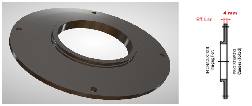
Customer adapter (preciseparts.com) back focus = 4mm (bolted)
Preciseparts.com has all our products on file, therefore they can make any custom adapter you may need for mechanical connection of your ONAG with other equipments, such as telescopes, focusers, cameras, FWs, and more …).

Preciseparts.com ONAG XM to SBIG STX/FW Adapter
Guider ATIK460EX (monochrome) optical back focus = 13mm
GBF = 13mm
Differential back focus DBF = 72 – 13 = 59 mm positive!
By calculation:
The ONAG® XM BFO is 33mm therefore to be parfocal one needs a spacer at the ONAG® GP with a length of:
59 – 33 = 26mm (ONAG® helical focuser half extended).
Using the table above (IBF = 72, GBF = 13):
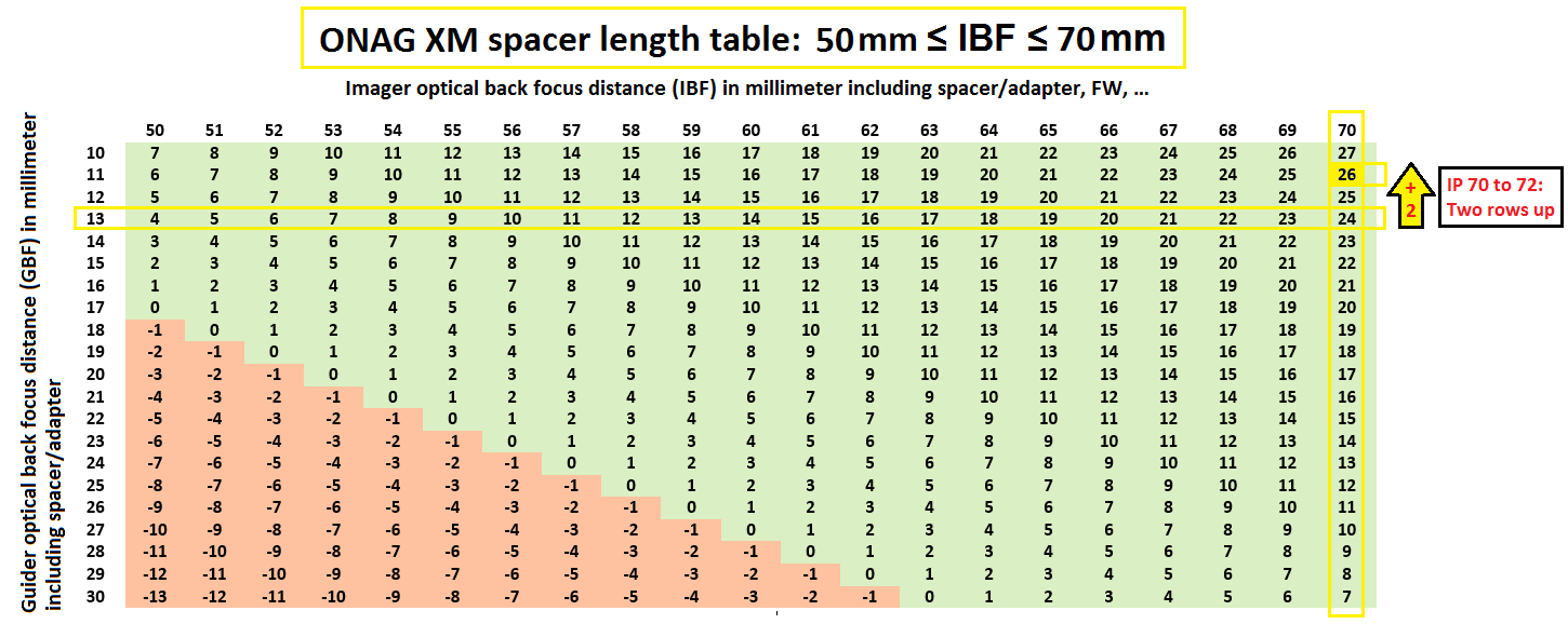
IBF = 72mm is outside of the table.
To find the spacer length of an IBF value larger than the maximum listed in the a table subtract one millimeter at the GBF value for each extra millimeter above the IBF table upper limit value, here 70mm.
With IBF=72mm we are two millimeters larger than the 70mm upper limit, which means that for GBF=13mm we need to look at GBF=11mm, or two rows up.
Reciprocally for an IBF value smaller than the minimum listed in the table add one millimeter at the GBF value for each extra millimeter below the IBF table lower limit value (one row down).
We found +26mm a positive (green) value therefore the spacer must be placed at the ONAG® GP.
With IBF=72mm the total optical back focus in this configuration is:
TOBF = IBF + OIBF = 72 + 68 = 140 mm
When having a large imaging camera and/or filter wheel at the IP it is important and strongly recommended to check/plan for the necessary clearance distances with the scope visual back and accessories, such as focuser, AO unit, …, if any.
Here is an example with the ONAG© XM and the above FW7STX + custom bolted adapter (4mm thick):
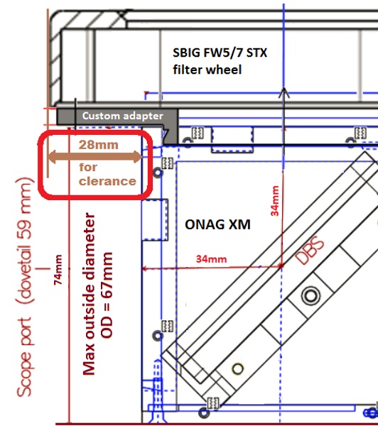
In this example the ONAG® XM must be at least at 28mm from the scope visual back (clearance for the FW).
Any spacer/adapter or accessory in between should have a maximum outside diameter (OD) of 67mm for at least 28mm from the ONAG® XM SP to insure proper clearance. All ONAG® dimensions are in millimeter with +/-1mm of tolerance.