How much focus error is too much?
Focusing errors are inevitable, however they can be reduced to a minimum with the correct focus strategy.
One fundamental question one should ask, and eventually answer, for astrophotography is how much focusing error is too much?
From the answer to this question depends grandly the quality of the images. Defocus translates to “fat” stars and larger FWHM, eventually degrading the image resolution.
Deconvolution and image restoration algorithms can enhance an image to some degrees, however inevitable noise and unknown defocus levels will eventually limit the achievable performances. Defocus leads to permanent loss of information (some spacial frequencies are gone for good), which in turn creates image artifacts while using such algorithms, like “ringing” near pattern transitions (hollow stars for instance), this is unavoidable.
The Critical Focus Zone:
A common and popular figure of merit for focus accuracy is the Critical Focus Zone (CFZ).
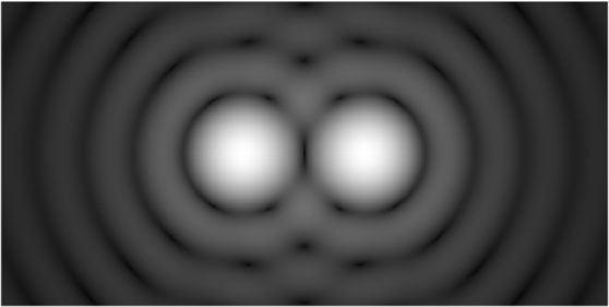
The CFZ is related to the telescope angular separation under diffraction limited conditions. This is known as the Rayleigh’s limit. In a nut shell it is the smallest angle for which two star diffraction patterns (Airy disks) can be resolved, as show below:
Above Rayleigh’s limit
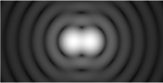
At Rayleigh’s limit (CFZ)
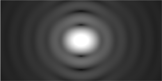
Below Rayleigh’s limit
The center image above shows the situation at the Rayleight’s limit, or CFZ, at the diffraction limit.
We could argue that the CFZ under such a condition is not enough, the most right image above would be a better choice as far as star shape goes (FWHM and roundness).
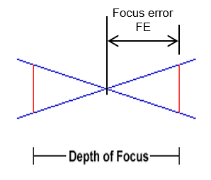
The right side figure here defines the depth of focus DF as twice the focus error FE for a light cone converging at the scope focal plane (the intersection of the blue lines in the figure).
DF = 2 x FE
The CFZ DF is defined as:
CFZ = +/- 2.44 x F2 x lambda = 4.88 x F2 x lambda
Where F is the scope F/# and lambda the light wavelength in nm.
Depth of Focus
The defocus wave front error:
A better approach, and figure of merit, for defocus is its related wave front error.
For small defocus the wave front error is quadratic in nature.
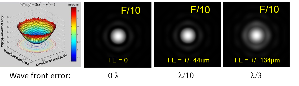
Below the point spread function (PDF), or Airy disk, for a F/10 telescope with various wave front errors (in lambda):
- Zero error => FE = 0
- Lambda/10 error => FE = +/- 44 microns
- Lambda/3 error => FE = +/- 134 microns (CFZ)
The most right PSF corresponds to the CFZ, or Rayleight’s limit, discussed above, which leads to about a lambda/3 wave front error.
In this case the PSF central peak and its first ring are already fused. On the other hand the lambda/10 error PSF is almost as good as the diffraction limit PSF (zero wave front error).
As far as the star quality (FWHM and roundness) goes the lambda/10 criteria is a better choice.
This should not be a surprise since the Rayleight’s limit has much to do with angular separation (resolving double star for instance) than the star shape.
Defocus wave front errors at F/10
Recommended focus errors:
From the above discussion, under diffraction limited close conditions, a good rule of thumb for the focus error is:
FEwave front < Lambda/10
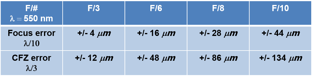
The table below provides FE for lambda/10 and lambda/3 (CFZ) defocus wave front errors versus the telescope F/#.
One can see that faster scopes (smaller F/#) lead to tighter FE.
Recommended maximum focus error (FE) versus scope F#
Focus shift with temperature:
Over a night the temperature can drop by several degrees, this is one of the major sources of telescope focus shift, beside flexure and play.
For instance a classical Schmidt-Cassegrain telescope (SCT) optical tube assembly (OTA) made of aluminum will shrink with drooping temperature. This will eventually bring both, primary and secondary, mirrors closer to each other.
The typical optical magnification m provided by both mirrors is about 5x for a SCT design, the related change in focus will be function of m2 leading to a factor 25x.
This means that for each micron of OTA shrinkage, the telescope focus shifts by as much as 25 microns.
Let’s take an example to get a better idea of what this does mean.
A SCT 11″ (aluminum) OTA at F/10 with a length of 610mm will shrink by:
23 * 0.61 = 14 microns per degree C
Here 23 is the aluminum coefficient of linear thermal expansion in micron per degree C.
The resulting focus shift will be:
14 x 25 = 350 microns (~0.014 inch) for each degree C
This should be compared with the above recommended focus errors, which is at F/10 around +/- 134 microns for the classical CFZ, and only +/-44 microns for the lambda/10 criteria.
Under near diffraction limited conditions the telescope focus needs to be adjusted each 44/350 = 0.13 degree C.
A 11″ SCT has a diffraction limit around 0.42″, under a average seeing condition of 2″, this means that we should consider refocusing each 0.13 x 2/0.42 = 0.6 degree C, or so.
Carbon fiber OTAs are usually better, however they are not totally immune against temperature shifts, as it can be seen on our “Real Time Autofocus – SharpLock” page.
Bottom line effective focus management and frequent adjustments are paramount to keep your image sharp.
In this context the ONAG and our patent pending real time autofocus technology, known as SharpLock, offer the unique solution for keeping you scope at its best focus, while imaging, all the time, every time.